Method for operating a wind turbine or a wind farm

a technology of wind turbines and wind farms, applied in the direction of reciprocating combination engines, electric generator control, greenhouse gas reduction, etc., can solve the problems of accelerated ageing and wear of components, and wind turbine failures in terms

Active Publication Date: 2014-12-04
WOBBEN PROPERTIES GMBH
View PDF6 Cites 8 Cited by
  • Summary
  • Abstract
  • Description
  • Claims
  • Application Information

AI Technical Summary

Benefits of technology

[0023]If, for example, there is a wind forecast in accordance with which the wind fluctuates constantly between 6 and 8 m/s for the next 30 minutes, i.e., in accordance with the forecast the wind does not fall below 6 m/s or else does not exceed 8 m/s, a reliable forecast can be established, for example, in accordance with wh

Problems solved by technology

The known disadvantage of wind energy consists in that it fluctuates with the wind, i.e., the electrical energy generated by the wind turbine can fluctuate depending on the present wind speed.
Thus, wind turbines fail in terms of many considerations with respect to grid management as generators for a base load because it is not possible to predict with sufficient probability the power input of the wind turbine to the grid.
The disadvantage of such a solution consists, however, in that even in the partial-load range of the wind turbine, the wind energy output of the w

Method used


Image

  • Method for operating a wind turbine or a wind farm
  • Method for operating a wind turbine or a wind farm
  • Method for operating a wind turbine or a wind farm

Examples


Embodiment Construction

[0039]Identical reference symbols can denote identical or else similar, non-identical elements below. For reasons of completeness, a wind turbine comprising a synchronous generator and having a gearless concept with a full converter will be explained below.

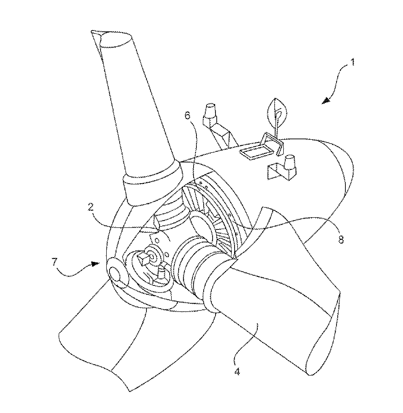
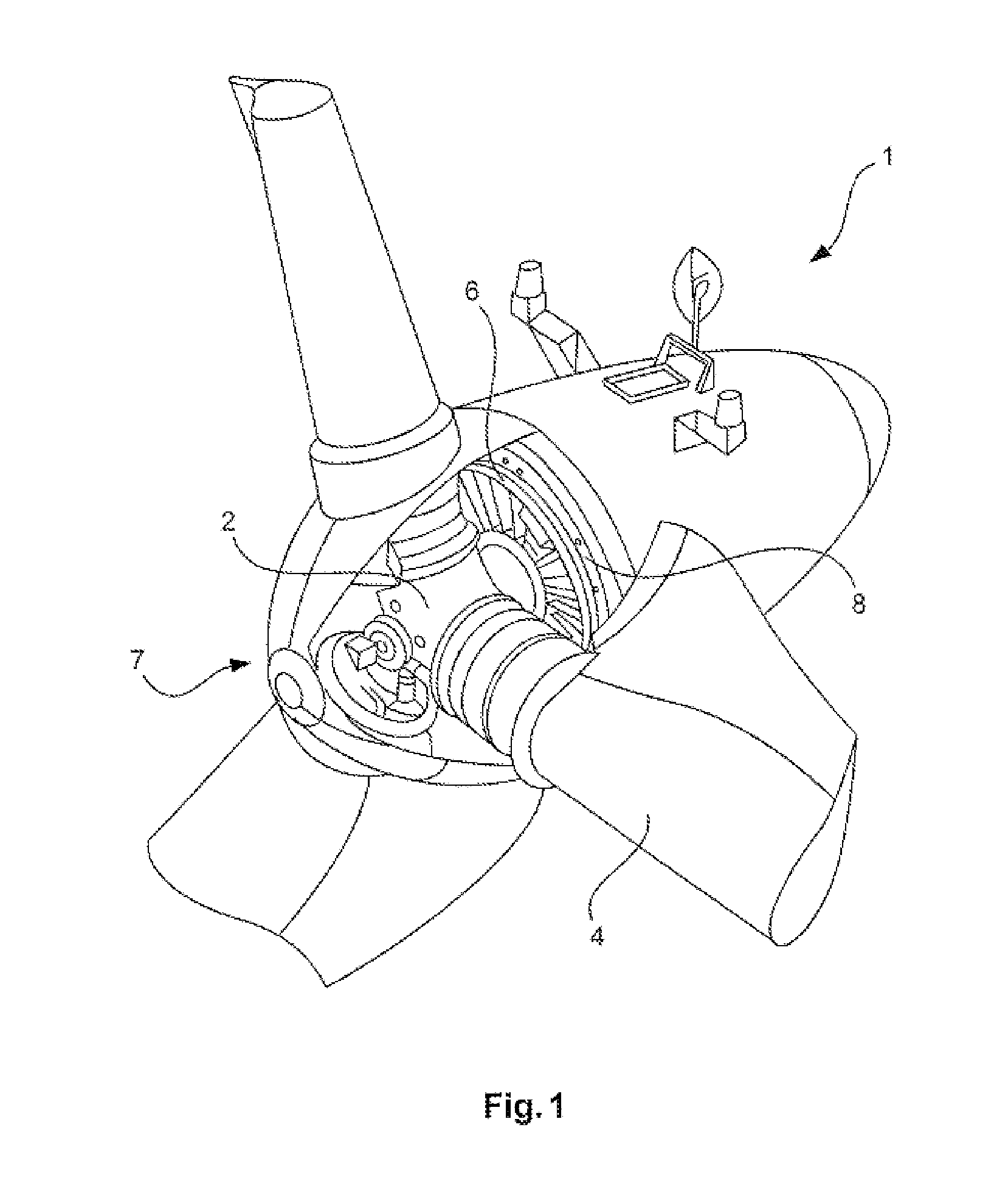
[0040]FIG. 1 shows, schematically, a wind turbine 1. In particular, a pod of a gearless wind turbine is shown as an example. The hub 2 is recognizable from the spinner which is illustrated as being partially open. Three rotor blades 4 are fastened at the hub 2, wherein the rotor blades 4 are only illustrated in their region close to the hub. The hub 2 with the rotor blades 4 forms an aerodynamic rotor 7. The hub 2 is fixedly connected mechanically to the rotor 6 of the generator, which can also be referred to as armature 6 and is referred to as armature 6 below. The armature 6 is mounted rotatably with respect to the stator 8.

[0041]The armature 6 is energized during its rotation relative to the stator 8, generally with a direct cu...


PUM


Abstract

Thus, a method for operating a wind turbine, a wind farm or the like and a power-to-gas unit connected electrically thereto is provided. The wind turbine or the wind farm generates electric power if there is sufficient wind and feeds this power into an electrical grid connected to the wind turbine or to the wind farm. Each wind turbine is operated with a predetermined power curve. Electric power is generated by the wind turbine or the wind farm once a first wind speed (starting wind) has been reached. The wind turbine or the wind farm is in a partial-load operating mode as long as the wind speed is between the first wind speed (starting wind) and a second wind speed (nominal wind). The wind turbine or the wind farm is in a nominal power range when the wind speed is in a range which is greater than the second wind speed (nominal wind speed). Electric power generated by the wind turbine or the wind farm, preferably at least a predetermined proportion of said power, is consumed in the power-to-gas unit, with the result that a combustible gas, in particular hydrogen and/or methane gas or the like, is generated in the power-to-gas unit. The proportion of the electric power which is generated by the wind turbine or the wind farm in the partial-load operating mode and is not consumed in the power-to-gas unit is set to be virtually constant for a predetermined time segment, for example 10 minutes or more, for example 1 hour.

Description

BACKGROUND[0001]1. Technical Field[0002]Wind turbines or wind farms comprising a multiplicity of wind turbines have long been known in a wide variety of forms, embodiments, sizes and variants.[0003]2. Description of the Related Art[0004]A wind turbine is an installation which transforms energy which is available in the wind into electrical energy by conversion. This electrical energy is primarily fed into an electric grid.[0005]The known disadvantage of wind energy consists in that it fluctuates with the wind, i.e., the electrical energy generated by the wind turbine can fluctuate depending on the present wind speed. However, this strictly speaking only applies in the partial-load range, i.e., in the range of the wind turbine between a first wind speed (starting wind) and a second wind speed (nominal wind). That is to say that if the wind strength is greater than the nominal wind speed, fluctuations in the wind speed which are above the nominal wind speed do not result in any fluctu...

Claims


Application Information

Patent Timeline
IPC IPC(8): F03D9/00F03D9/02
CPCF03D9/02F03D9/005F03D7/048F05B2220/61F05B2240/96F05B2270/1033F05B2270/404F03D9/257F03D9/19Y02E10/72Y02E60/36Y02E70/30
Inventor DE BOER, JOACHIM
Owner WOBBEN PROPERTIES GMBH
Why Eureka
Try Eureka