[0024]By repeating the operation of applying a
constant current while repeating the above method of the invention, it becomes possible to increase the current to be applied until a final target operation current level while repeatedly confirming that there is no
abnormality in electrolysis condition. As a result, a fluorine or fluoride gas can be generated very safely. The term “target operation current level” as used herein means a necessary and sufficient current value to be applied between the anode and
cathode for generating a required gas amount within the range up to a maximum current capacity applicable between the anode and cathode by the electrolytic power source of the generator.
[0030]If an excessive current is applied at a time because of hastened production on the production site in a
gas generator generating a fluorine or fluoride gas, the rate of formation of (CF)n, which causes polarization, according to the equation (7) among the reactions indicated by the equations (4) to (10) increases, hence polarization will be caused. In case of occurrence of this
abnormality, it is difficult to detect the electrolytic
voltage fluctuation based on an
abnormality due to a worsened electrode condition since the change due to current application is too rapid even when the electrolytic voltage between the anode and cathode is being measured. Even if this abnormality can be detected, the symptoms are already in a worst condition, so that it is difficult to avoid or eliminate the abnormal state or bring about a
recovery from that state by reducing the current, for instance. If the current to be applied at a time is excessively small, a very long period of time is required to attain the target operation current level and may cause a
delay in required
gas supply. Therefore, the current to be applied at a time should be not more than 5 A / dm2, preferably within the range of 1 to 3 A / dm2, relative to the effective electrolytic surface area on the anode, whereby any
delay in detection or worsening in condition can be prevented.
[0032]In large gas generators for generating a fluorine or fluoride gas whose current capacity is 1,000 A to 5,000 A, for instance, the electrodes generally comprise 10 to 32 plates. As for the method of electrode mounting, one to ten plates are fixed to each of a plurality of current collectors. Therefore, in case of the occurrence of an abnormality, the state thereof can be detected by measuring the range of
voltage fluctuation between the anode and cathode. When, however, the electrode and / or electrolyzer will not return to a
normal state in
spite of such operation as decreasing the current application, the abnormality may generally have begun from a part of the whole number of electrode plates. Therefore, by employing a plurality of power sources and measuring the range of electrolytic
voltage fluctuation between the anode and cathode of each
current collector unit for each of the respective power sources, it becomes possible to specify the site of abnormality occurrence with ease. Once the abnormality site can be specified, it becomes possible to operate the power source connected to the abnormality site alone according to the degree of abnormality while operating the other power sources under predetermined ordinary conditions. Thus, by increasing the number of electrolytic power sources but decreasing the capacity of each of the respective power sources relative to the current capacity of the generator, it becomes possible to finely control the generator depending on the respective states of the plurality of electrodes.
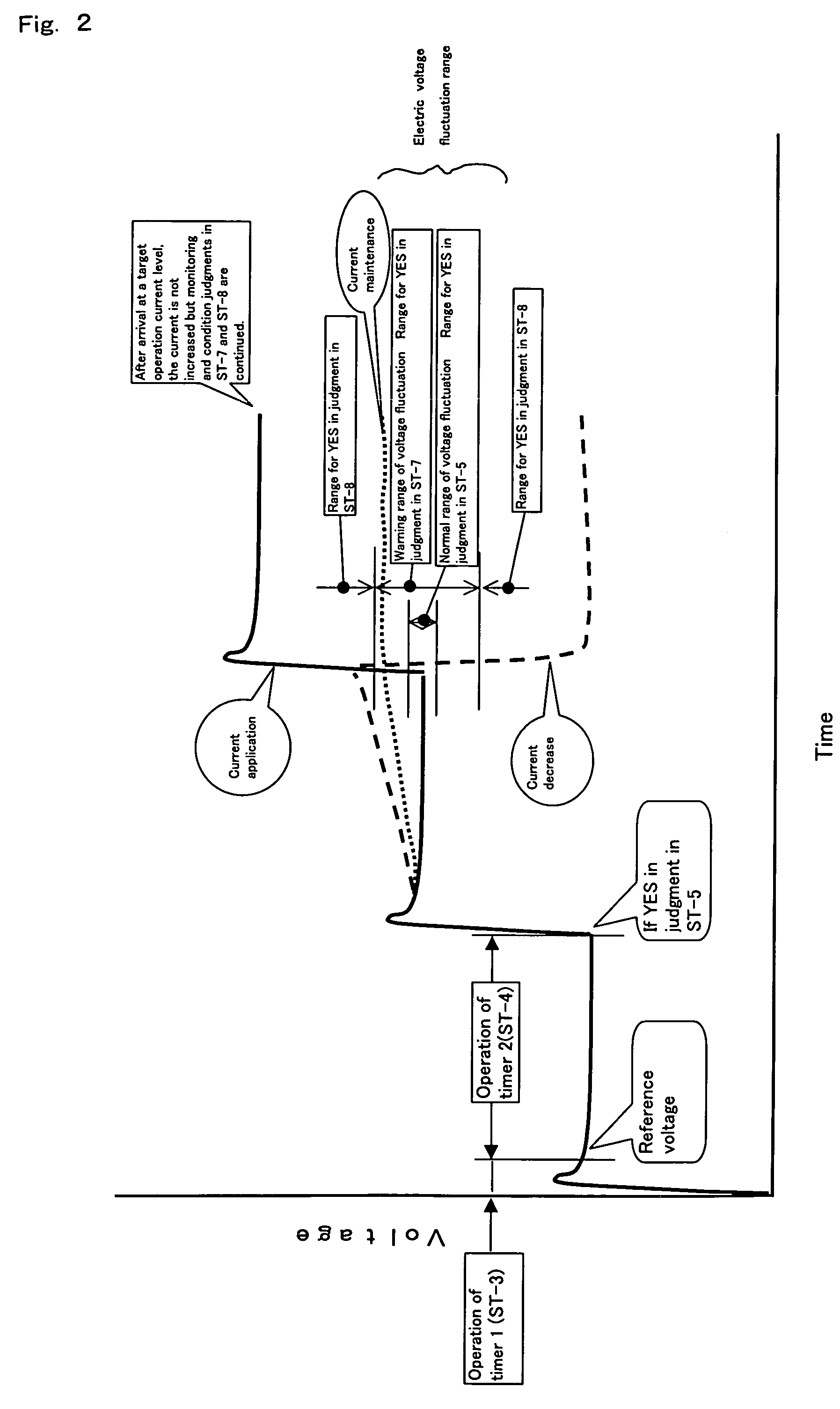
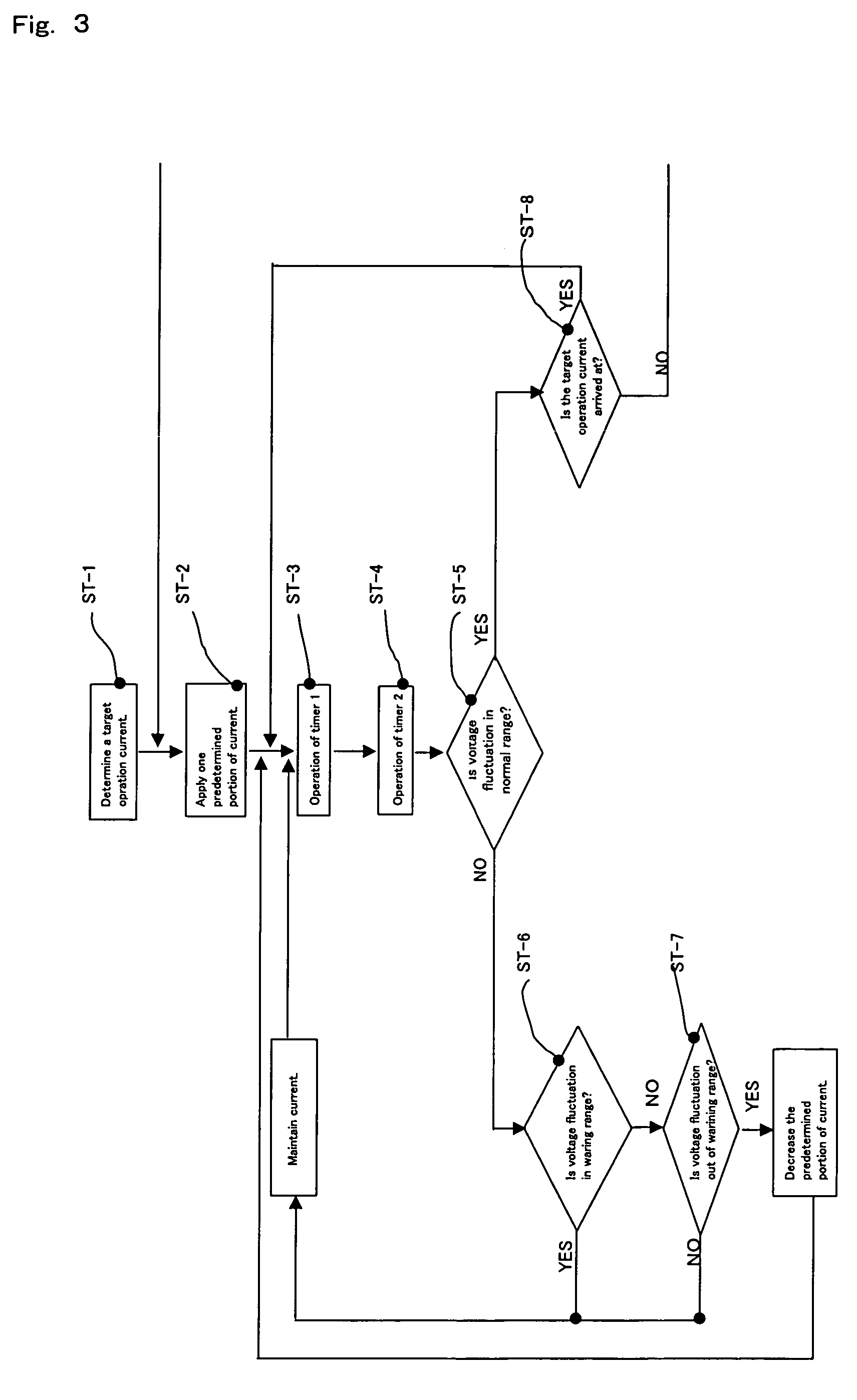
[0036]When the range of electrolytic voltage fluctuation as shown in FIG. 2 is measured by the first measuring means, the second measuring means and the means for measuring the electrolytic voltage between the anode and cathode and found to be within the
normal range, a certain current is further applied (ST-2), the same measurements are repeated and, finally, current application is carried out until the operation current level intended of the power source employed in the
gas generator for generating a fluorine or fluoride gas to thereby generate a required amount of a fluorine or fluoride gas. If the range of electrolytic voltage fluctuation between the anode and cathode is in the warning range, further electrolytic current application (ST-6) is suspended, the electrolytic voltage fluctuation range measurement is repeated by the first measuring means, the second measuring means and the means for measuring the electrolytic voltage between the anode and cathode (ST-6, ST-7) and, when the fluctuation range can be judged to be within the
normal range based on the measurement results, further electrolytic current application is restarted. If the range of electrolytic voltage fluctuation is in the abnormality range (ST-7), the constant electrolytic current applied previously is reduced to the level before application, the electrolytic voltage fluctuation range measurement is carried out using the first measuring means, the second measuring means and the means for measuring the electrolytic voltage between the anode and cathode and, when the fluctuation can be judged to be within the
normal range based on the measurement results, electrolytic current application is restarted. When the fluctuation is judged to be in the warning range, the warning range procedure mentioned above is followed. When an apparatus, or
system, having all of these functions is used, it is possible to select a target operation current value and automatically apply an
electric current in constant amounts between the anode and cathode until the intended current amount is reached and, after arrival at the intended current amount, automatic operation is still possible by continuing the current control in the same manner. It becomes also possible to allow the electrolysis conditions to proceed always stably. In case of abnormality occurrence during operation, the abnormality can be detected early depending on the results of measurement of the range of electrolytic voltage fluctuation between the anode and cathode and the operation condition can be prevented from worsening by adjusting the current amount.
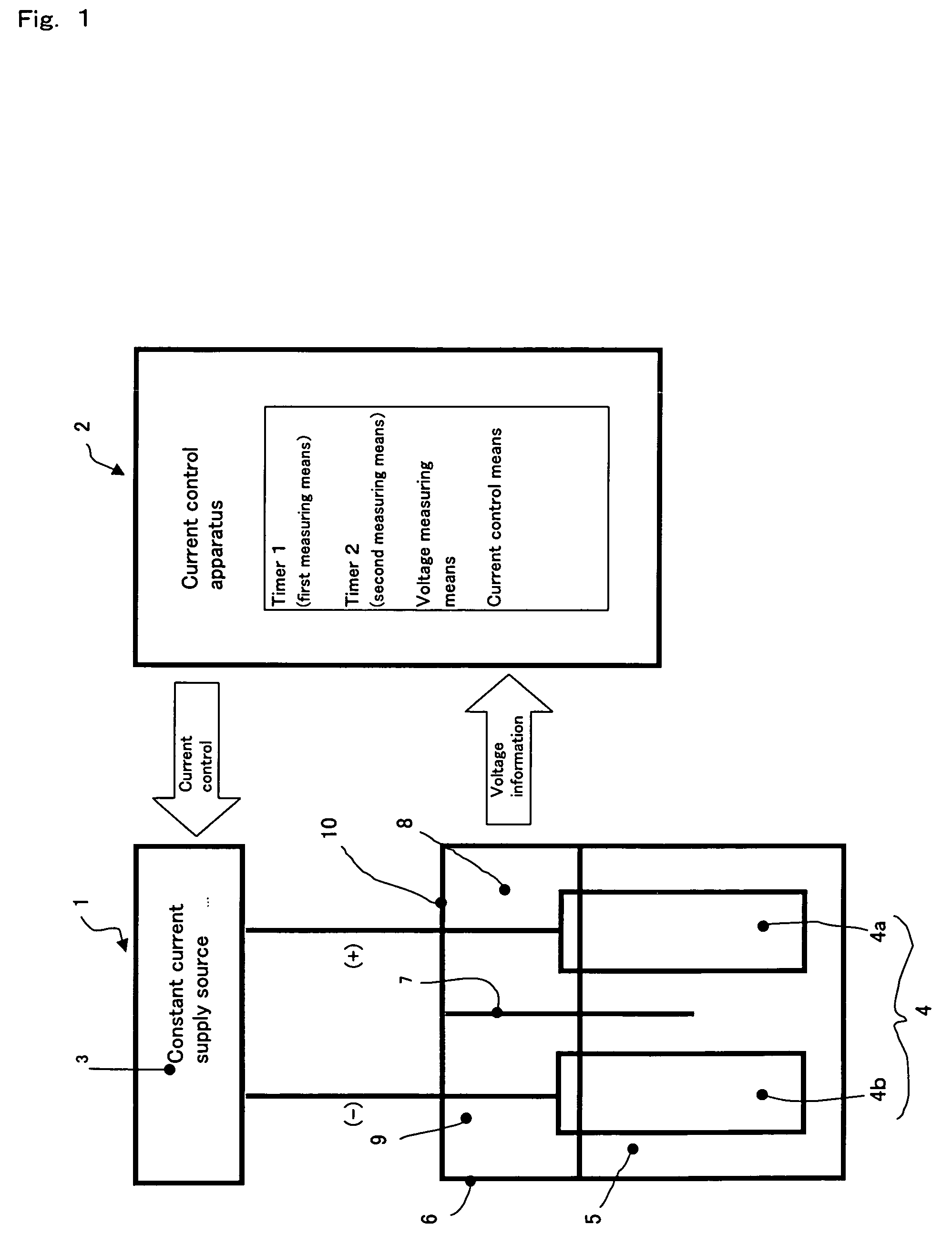
[0038]By employing a plurality of
constant current supply sources and measuring the range of electrolytic voltage fluctuation between the anode and cathode of each
current collector unit for the respective power sources, it becomes easy to specify the site of abnormality occurrence. Once the abnormality site can be specified, it becomes possible to operate the power source connected to the abnormality site alone according to the degree of abnormality while operating the other power sources under predetermined ordinary conditions. Thus, by increasing the number of electrolytic power sources but decreasing the capacity of each of the respective power sources relative to the current capacity of the generator, it becomes possible to finely control the generator depending on the respective states of the plurality of electrodes.

