
Filler neck apparatus for preventing fuel from mixing

a technology of fuel mixing and flange, which is applied in the direction of liquid handling, transportation and packaging, packaging goods types, etc., can solve the problems of mechanical abrasion, the inability of the fuel supply gun of the diesel car to be inserted into the fuel injection hole of the gasoline car,

Active Publication Date: 2014-12-04
HYUNDAI MOTOR CO LTD
View PDF23 Cites 15 Cited by
  • Summary
  • Abstract
  • Description
  • Claims
  • Application Information

AI Technical Summary

Benefits of technology

The invention is a device that prevents fuel from mixing in a car's fuel tank. It is designed to lock or unlock based on the diameter of the fuel filling gun using protrusions on the sides of the device. This prevents gasoline from contaminating the fuel tank and ensures that the engine runs properly. The device includes a rotating stopper with protrusions that lock or unlock the device. This prevents the need for a complicated and expensive system to prevent fuel from mixing.

Problems solved by technology

However, due to a difference between a diameter of the fuel supply gun and a diameter of a fuel injection hole caused by a gasoline or diesel fuel, the fuel supply gun for the diesel car cannot be inserted into the fuel injection hole for the gasoline car.
However, the fuel supply gun for the gasoline car can be inserted into the fuel injection hole for the diesel car so that the gasoline fuel may be supplied to the diesel car due to an oil-filling mistake.
In this case, if a diesel engine is driven in a state in which the gasoline fuel flows in a fuel system for the diesel car, the diesel car may stall during driving and may stop suddenly, mechanical abrasion caused by the gasoline fuel may occur, and when the diesel car stalls during driving, components relating to the gasoline fuel must be replaced with new one.

Method used


Image

  • Filler neck apparatus for preventing fuel from mixing
  • Filler neck apparatus for preventing fuel from mixing
  • Filler neck apparatus for preventing fuel from mixing

Examples


Embodiment Construction

[0035]Reference will now be made in detail to various embodiments of the present invention(s), examples of which are illustrated in the accompanying drawings and described below. While the invention(s) will be described in conjunction with exemplary embodiments, it will be understood that the present description is not intended to limit the invention(s) to those exemplary embodiments. On the contrary, the invention(s) is / are intended to cover not only the exemplary embodiments, but also various alternatives, modifications, equivalents and other embodiments, which may be included within the spirit and scope of the invention as defined by the appended claims.

[0036]The present invention will now be described more fully with reference to the accompanying drawings, in which exemplary embodiments of the invention are shown, so that one of ordinary skill in the art can easily embody the present invention.

[0037]The present invention relates to a filler neck device for preventing fuel from m...


PUM

PropertyMeasurementUnit
rotation protrusionaaaaaaaaaa
lengthaaaaaaaaaa
insertion forceaaaaaaaaaa

Abstract

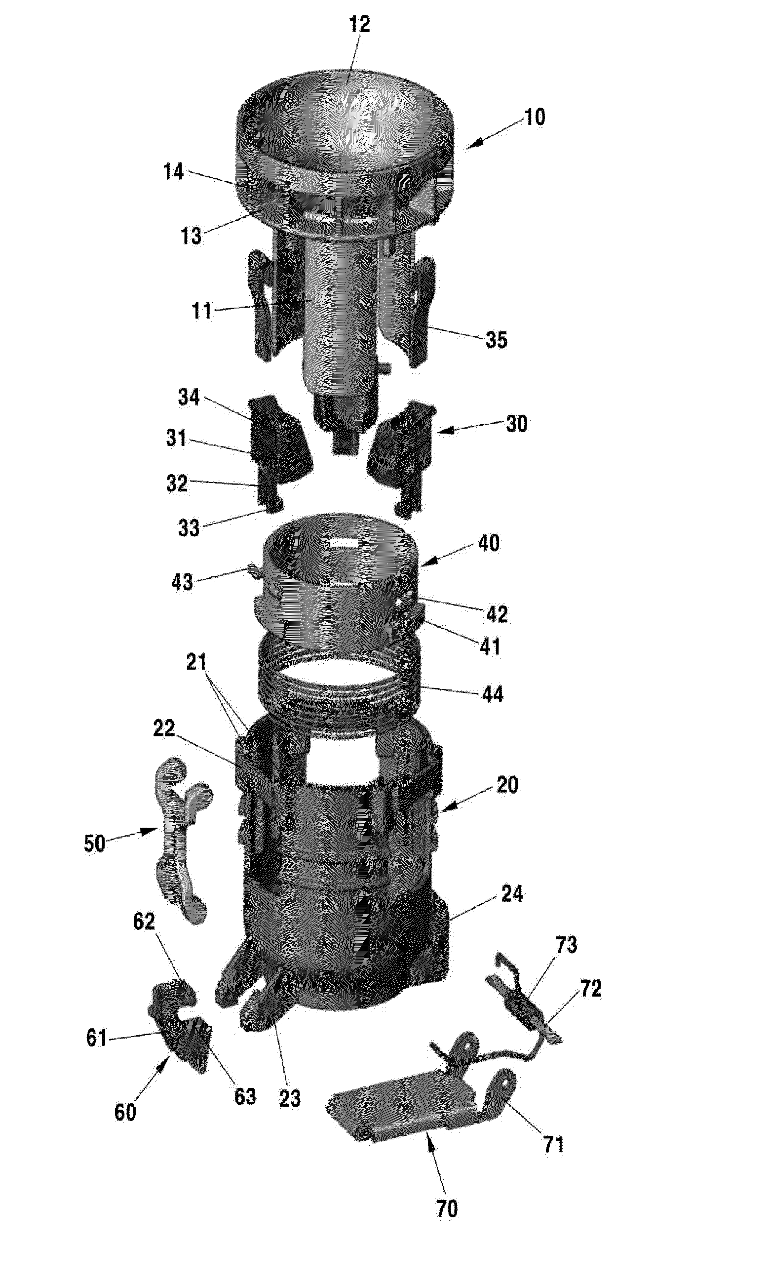
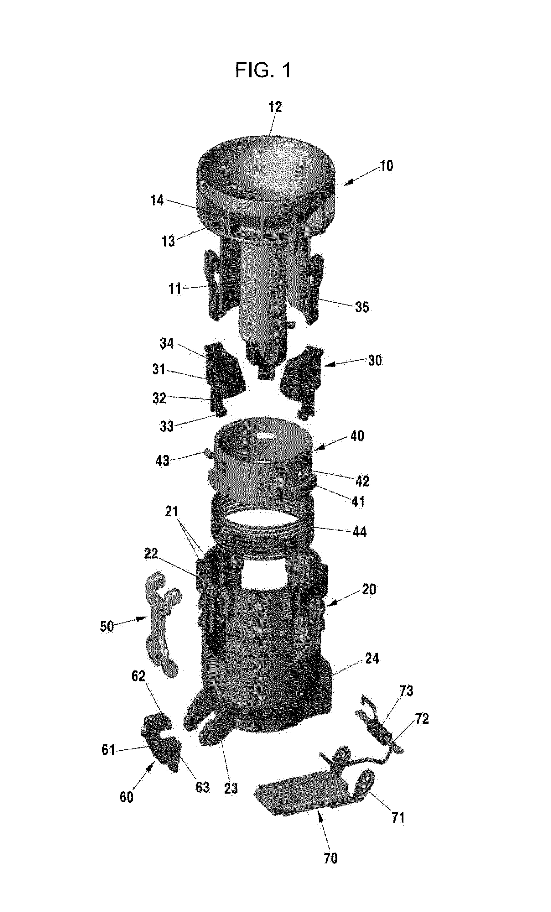
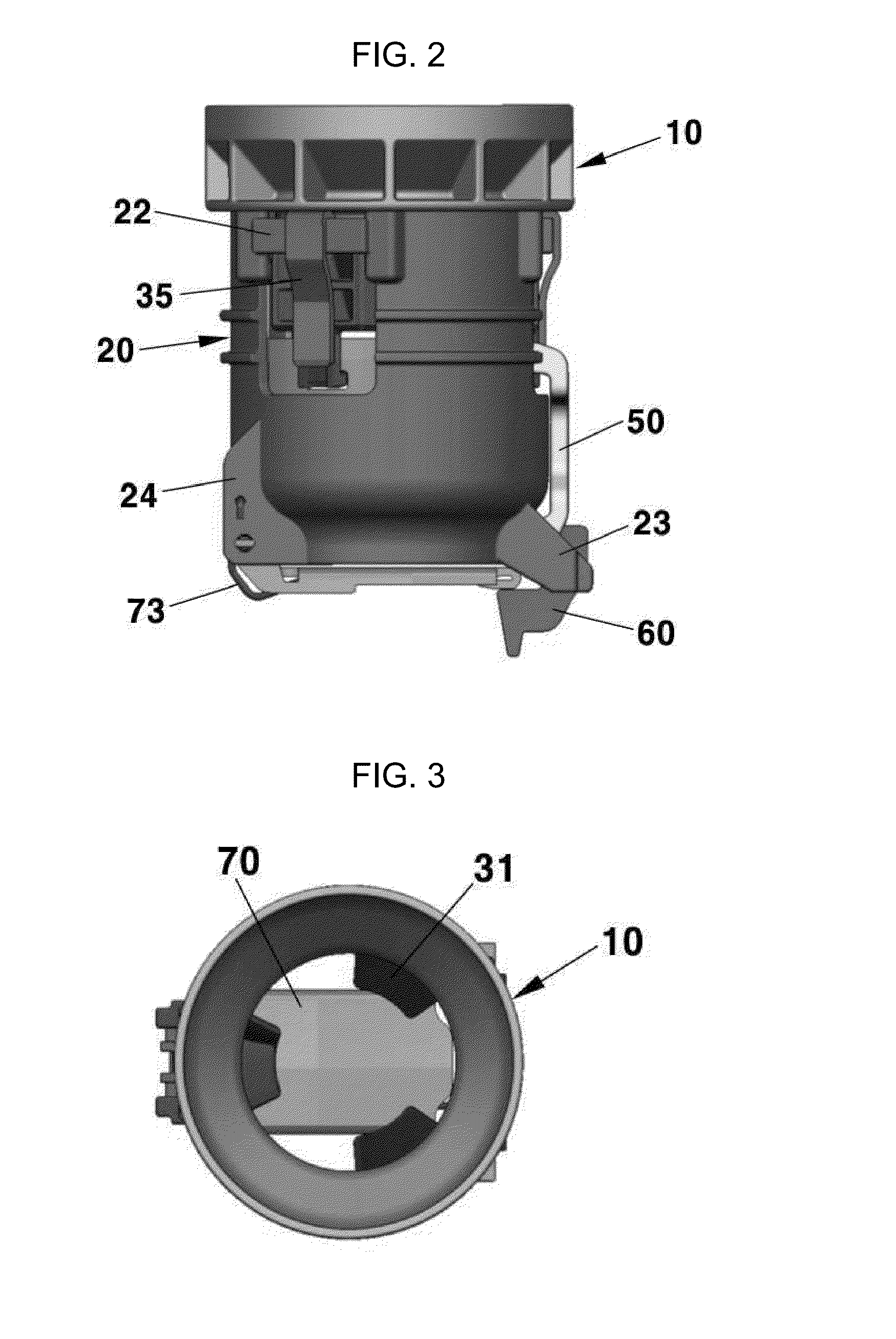
A filler neck apparatus may include a housing into which a fuel filling gun is selectively inserted, a rotation protrusion pivotally mounted on a side of the housing and elastically biased in a direction, wherein the rotation protrusion contacts with the fuel filling gun while the fuel filling gun is inserted into the housing, a slider slidably installed in the housing and elastically biased in a direction wherein the slider is selectively coupled to the rotation protrusion, and wherein a locked state of the slider is released by the rotation protrusion and is movable in a direction when the slider is released from the rotation protrusion, a flapper pivotally mounted on the housing and opening or closing the bottom end of the housing by the fuel filling gun, a stopper pivotally mounted on the housing and selectively locking the flapper, and a link pivotally connecting the slider and the stopper.

Description

CROSS-REFERENCE TO RELATED PATENT APPLICATION[0001]This application claims the benefit of Korean Patent Application No. 10-2013-0060064, filed on May 28, 2013, the entire contents of which is incorporated herein for all purposes by this reference.BACKGROUND OF THE INVENTION[0002]1. Field of the Invention[0003]The present invention relates to a filler neck device for preventing a gasoline fuel from mixing in a diesel car.[0004]2. Description of Related Art[0005]In general, a fuel tank for storing fuel required for combustion of an engine is provided in a car, and the fuel tank is connected to a fuel filling pipe, and a fuel filler neck for a car that represents a fuel supply hole is provided at an end of the fuel filling pipe so as to supply fuel.[0006]A diameter of a fuel supply gun for injecting fuel into the fuel filler neck varies depending on a gasoline or diesel fuel, and the supply speed of fuel also varies.[0007]Generally, the diameter of the fuel supply gun for injecting the...

Claims


Application Information

Patent Timeline
Patent Type & Authority Applications(United States)
IPC IPC(8): B60K15/04
CPCB60K15/04B60K2015/0483B60K2015/0461B60K15/073
Inventor RYU, BU YEOLCHOI, PIL SEONLEE, BO SUNG
Owner HYUNDAI MOTOR CO LTD
Learn More