Cable positioning device and charger using same

a positioning device and charger technology, applied in the direction of charging stations, coupling device connections, transportation and packaging, etc., can solve the problems of non-elastic deformation of the positioning device and the further tightening of the cable, prolonging the lifespan of the charger

Active Publication Date: 2014-12-04
KS TERMINALS INC
View PDF3 Cites 7 Cited by
  • Summary
  • Abstract
  • Description
  • Claims
  • Application Information

AI Technical Summary

Benefits of technology

[0006]The present invention has been accomplished under the circumstances in view. It is the main object of the present invention to provide a cable positioning device fo

Problems solved by technology

Thus, a cable installation worker can use a tool to crimp the cable positioning device, causing the cable positioning device to deform non-elastically and to further tightly fit the cable.
When a user uses the charger, the cable is tightly fitted by the cable positioning device and the attaching force produced from the abutment be

Method used


Image

  • Cable positioning device and charger using same
  • Cable positioning device and charger using same
  • Cable positioning device and charger using same

Examples


Embodiment Construction

[0016]In order to better understand the features of the present invention, a preferred embodiment is set forth hereby with reference to the annexed drawings.

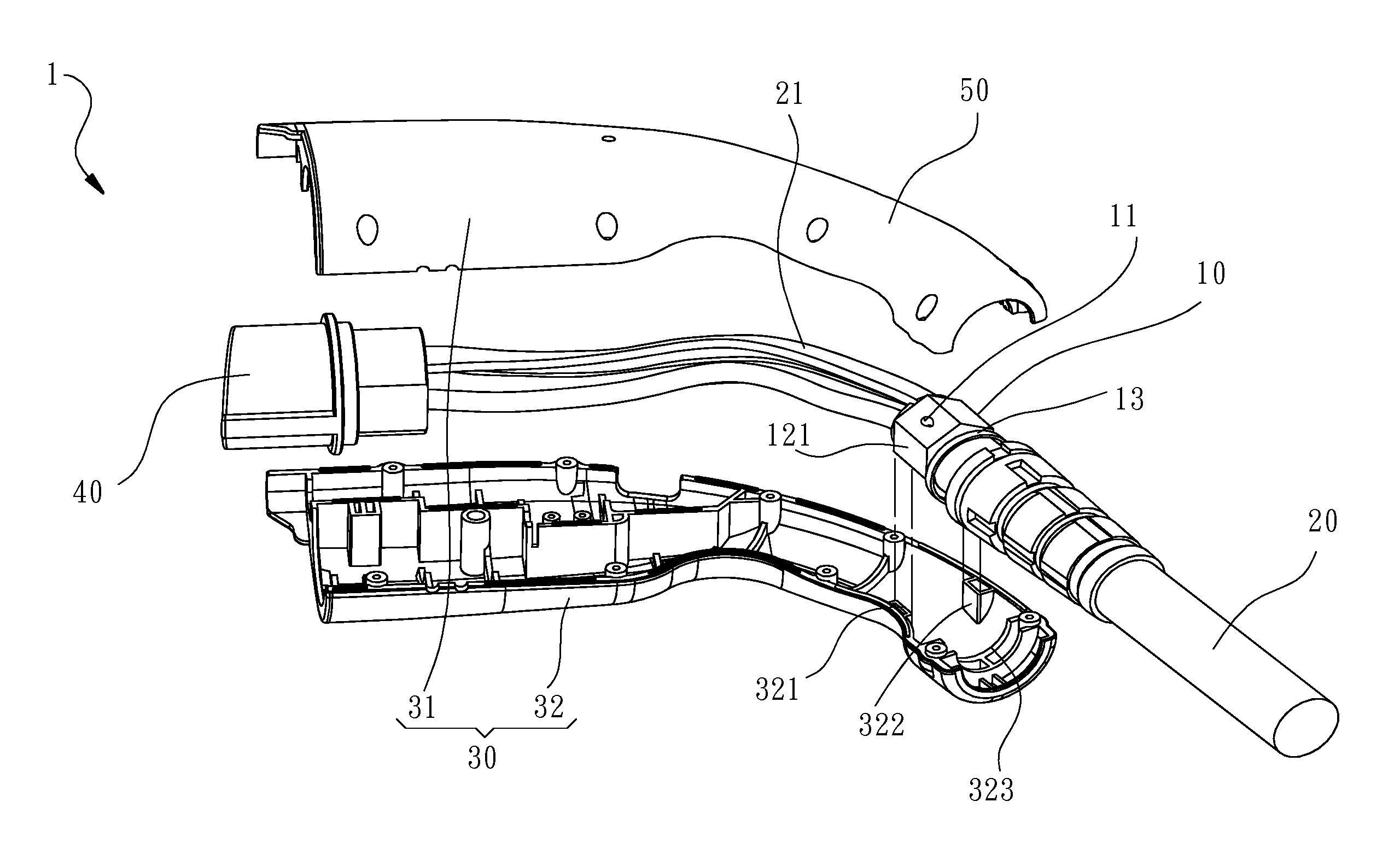
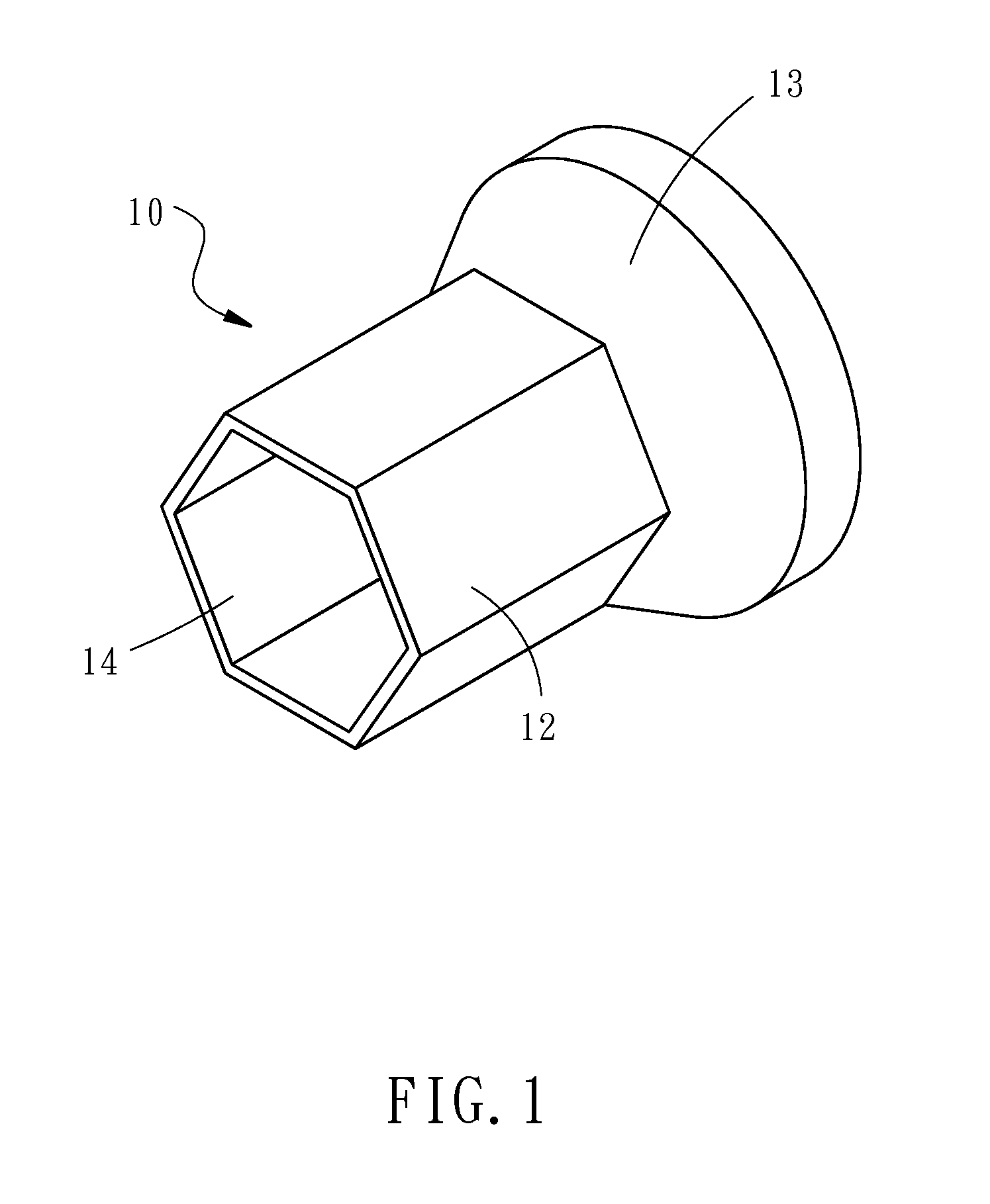
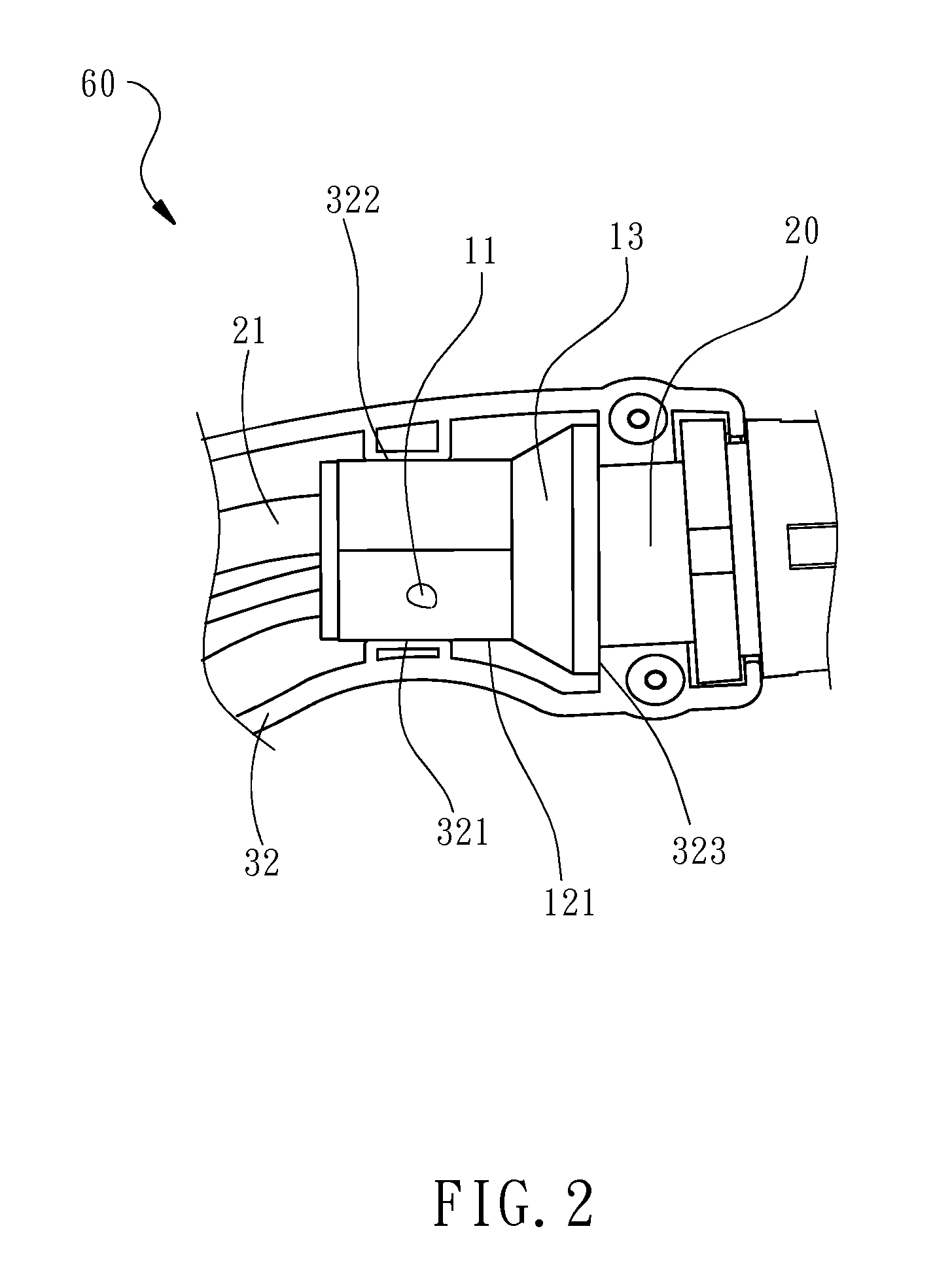
[0017]Referring to FIGS. 1-4, a charger 1 in accordance with the present invention is shown. The charger 1 comprises a connector body 30, a grip 50 formed in the connector body 30, a mounting structure 60 formed integrally inside the grip 50, a cable 20 inserted through the grip 50, and a cable positioning device 10 mounted in the mounting structure 60 for securing the cable 20. The cable positioning device 10 comprises a column 12 having a polygonal cross section, a passage 14 defined within the column 12 for the insertion of the cable 20. The column 12 can be forced to deform non-elastically and to further tightly fit the cable 20. Further, the column 12 has at least one peripheral surface abutted against an inside wall of the mounting structure 60.

[0018]The details of the relationship between components of the preferred embod...


PUM


Abstract

A cable positioning device and a charger using the cable positioning device is disclosed to include a cable positioning device mounted in a mounting structure inside the charger to secure a cable. The cable positioning device includes a polygonal column that can be forced by an external pressure to deform non-elastically and to further tightly fit the cable, having at least one surface thereof abutted against an inner wall of the mounting structure in the axial direction of the cable to prevent displacement of the cable positioning device and the internal electric wires of the cable due to accidental twisting of the external part of the cable, improving the cable installation efficiency.

Description

BACKGROUND OF THE INVENTION[0001]1. Field of the Invention[0002]The present invention relates to charger technology and more particularly, to a cable positioning device for use in a charger to secure a cable, preventing the cable from rotation due to twisting or rotation of an external part of the cable of the charger upon movement of the charger, and improving cable installation efficiency.[0003]2. Description of the Related Art[0004]Cables are known as essential components of many machines for use in transmitting electrical signals. To enhance signal transmission stability, U.S. Pat. No. 4,394,531 discloses a device for reducing vibration of a transmission line, entitled “Transmission line assembly including means for reducing vibrations and method of making same”. This design includes an outer tubular sheath having an inner surface and a plurality of protruding wall members mounted along the inner surface of the tubular sheath securing a transmission line by the friction of the a...

Claims


Application Information

Patent Timeline
IPC IPC(8): H02G15/00H02J7/00
CPCH02J7/0042H02G15/00H02G15/007H01R13/565H01R13/5808Y02T10/7072Y02T90/14B60L53/16Y02T10/70
Inventor LIN, CHANG-YI
Owner KS TERMINALS INC
Why Eureka
Try Eureka