Endoscope system

a technology of endoscope and endoscope, which is applied in the field of endoscope system, can solve the problems of image collapse and increase and achieve the effect of reducing the burden on the control section of the processor uni

Inactive Publication Date: 2014-12-04
FUJIFILM CORP
View PDF4 Cites 47 Cited by
  • Summary
  • Abstract
  • Description
  • Claims
  • Application Information

AI Technical Summary

Benefits of technology

[0030]According to the endoscope system of the present invention, a combination of sequence pattern which includes a plurality of parameters, each corresponding to imaging conditions of the image sensor on a frame-by-frame or a plurality of frames-by-frames basis according to the type of light source and predetermined control signal to be outputted from the control section is preset in the sequence pattern setting section of the endoscope unit, a plurality of types of parameters and imaging conditions correspond to each parameter are set in the imaging condition setting section of the endoscope unit in association with each other, and the imaging control section of the endoscope unit obtains the sequence pattern based on the control signal outputted from the control section of the processor unit, sequentiall

Problems solved by technology

If the receive timing of the control signal by the image sensor is delayed due to, for example, the occurrence of certain interrupt processing in a control section of the processor unit, the imaging condition is changed in the middle of the imaging op

Method used


Image

  • Endoscope system
  • Endoscope system
  • Endoscope system

Examples


Embodiment Construction

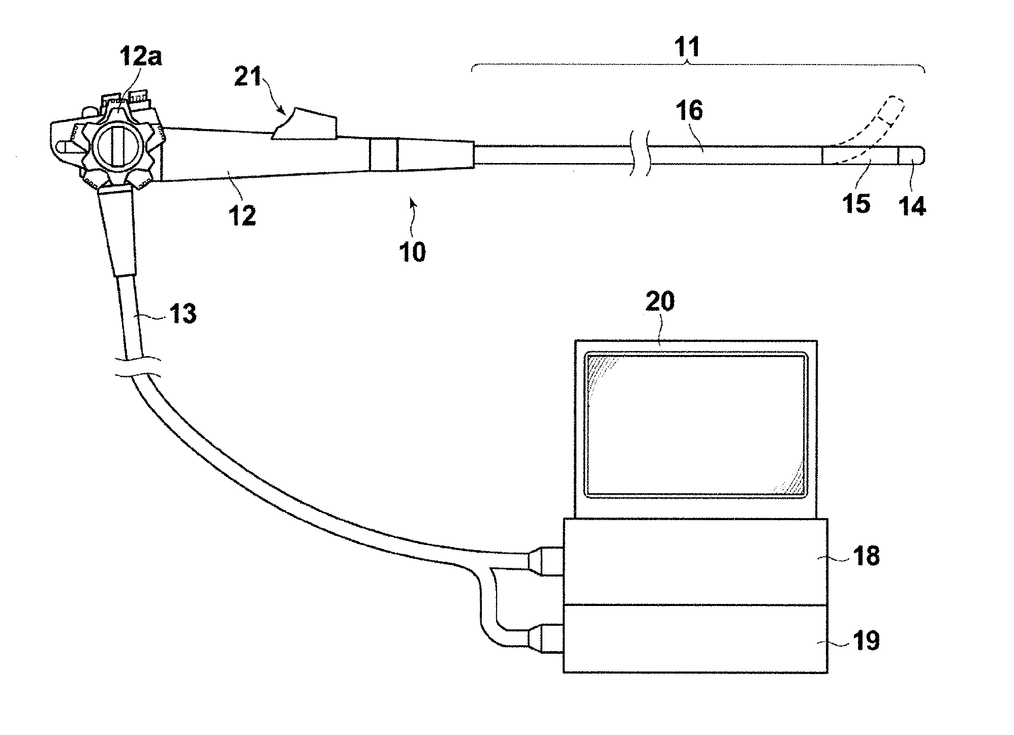
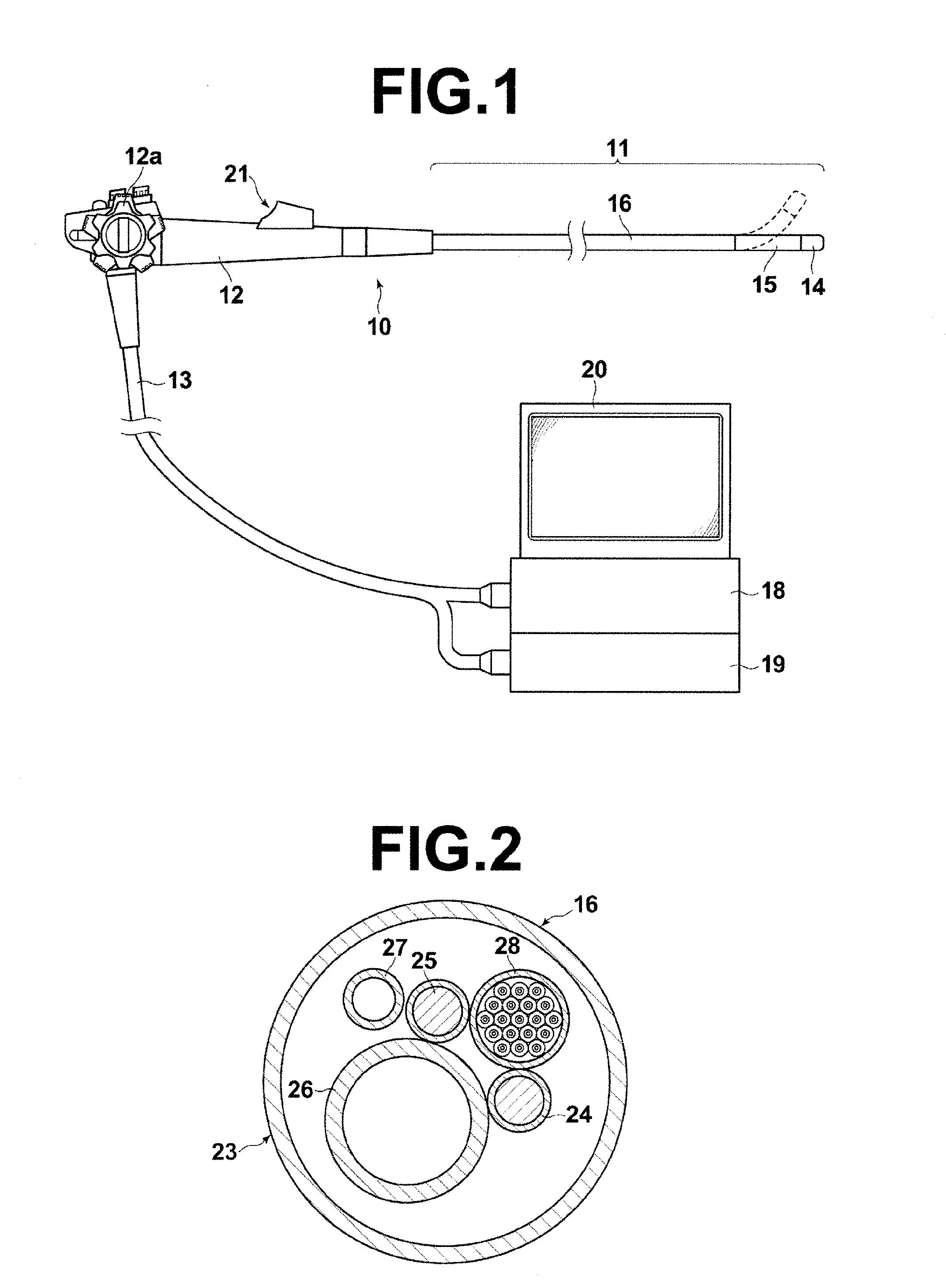
[0048]Hereinafter, an embodiment of the endoscope system of the present invention will be described in detail with reference to the accompanying drawings. The endoscope system of the present embodiment has a characteristic feature in the control method of imaging conditions for the image sensor according to the switching of a plurality of types of light sources. But the configuration of the entire system will be described first. FIG. 1 is an external view of the endoscope system of the present embodiment, illustrating the schematic configuration thereof.

[0049]As illustrated in FIG. 1, the endoscope system of the present embodiment includes an endoscope unit 10, a universal cable 13 whose one end is to be connected to the endoscope unit 10, a processor unit 18 and a light source unit 19 to which the other end of the universal cable 13 is to be connected, and a monitor 20 that displays an image based on image signals outputted from the processor unit 18.

[0050]The endoscope unit 10 inc...


PUM


Abstract

An endoscope unit includes a sequence pattern setting section in which a combination of sequence pattern which includes a plurality of parameters, each corresponding to imaging conditions of the image sensor on a frame-by-frame basis according to the type of the light source and control signal is set, an imaging condition setting section in which imaging conditions corresponding to each parameter are set, and an imaging control section that obtains the sequence pattern based on a control signal outputted from a control section of a processor unit, reads out the imaging conditions corresponding to each parameter included in the sequence pattern from the imaging condition setting section, and controls the imaging operation of the image sensor on a frame-by-frame basis based on the imaging conditions.

Description

CROSS-REFERENCE TO RELATED APPLICATIONS[0001]The present application claims priority under 35 U.S.C. §119 to Japanese Patent Application No. 2013-117892 filed on Jun. 4, 2013. Each of the above application(s) is hereby expressly incorporated by reference, in its entirety, into the present application.BACKGROUND OF THE INVENTION[0002]1. Field of the Invention[0003]The present invention relates to an endoscope system in which light of different wavelengths is projected onto an observation target area by sequentially switching a plurality of types of light sources and image signals due to the projection of each light are obtained on a frame-by-frame basis.[0004]2. Description of the Related Art[0005]Endoscope systems for observing tissues in the bodies have been widely known and electronic endoscope systems that obtain a visual image by imaging an observation target area by the use of an image sensor and display the visual image on a monitor screen are widely put into practical use.[00...

Claims


Application Information

Patent Timeline
IPC IPC(8): A61B1/06H04N5/374A61B1/04
CPCA61B1/0661H04N5/374A61B1/043A61B1/045A61B1/0638A61B1/0655H04N23/555H04N23/667H04N23/74
Inventor YANO, TAKASHI
Owner FUJIFILM CORP
Why Eureka
Try Eureka