Low cost optical high speed discrete measurement system

a high-speed, discrete technology, applied in the field of low-cost optical high-speed discrete measurement system, can solve the problems of difficult implementation, high magnification and limited field of view of imaging individual droplets with conventional optics, and difficult to measure changes in droplet location or siz

Active Publication Date: 2014-12-04
BIO RAD LAB INC
View PDF6 Cites 35 Cited by
  • Summary
  • Abstract
  • Description
  • Claims
  • Application Information

AI Technical Summary

Benefits of technology

[0012]In a second aspect of the present invention, a method is provided for determining a velocity or an inflation rate of a droplet passing through a microfluidic channel using the system described above. The method includes the following steps: illuminating the droplet with a first flash of light emitted by the multicolor light source, wherein the first flash of light includes light of a first wavelength band; acquiring a first image of the droplet when the droplet is illuminated with the first flash of light; allowing an amount of time to pass; illuminating the droplet with a second flash of light emitted by the multicolor light source, wherein the second flash of light includes light of a second wavelength band different from the first wavelength band; acquiring a second image of the droplet when the droplet is illuminated with the second flash of light, wherein the first image and the second image are acquired (i) using the detector and (ii) as part of the same video frame or the same photographic exposure; calculating a change in position or size of the droplet between the first image and the second image; and dividing the change in position or size of the droplet by the amount of time, thereby determining a velocity or an inflation rate of the droplet passing through the microfluidic channel between the first image and the second image.

Problems solved by technology

Measuring changes in droplet location or size is challenging, however, because of the small dimensions of microfluidic devices and the droplets themselves.
Imaging individual droplets with conventional optics requires a high level of magnification and a limited field of view.
These solutions are expensive and difficult to implement.

Method used


Image

  • Low cost optical high speed discrete measurement system
  • Low cost optical high speed discrete measurement system
  • Low cost optical high speed discrete measurement system

Examples


working example

A. Working Example

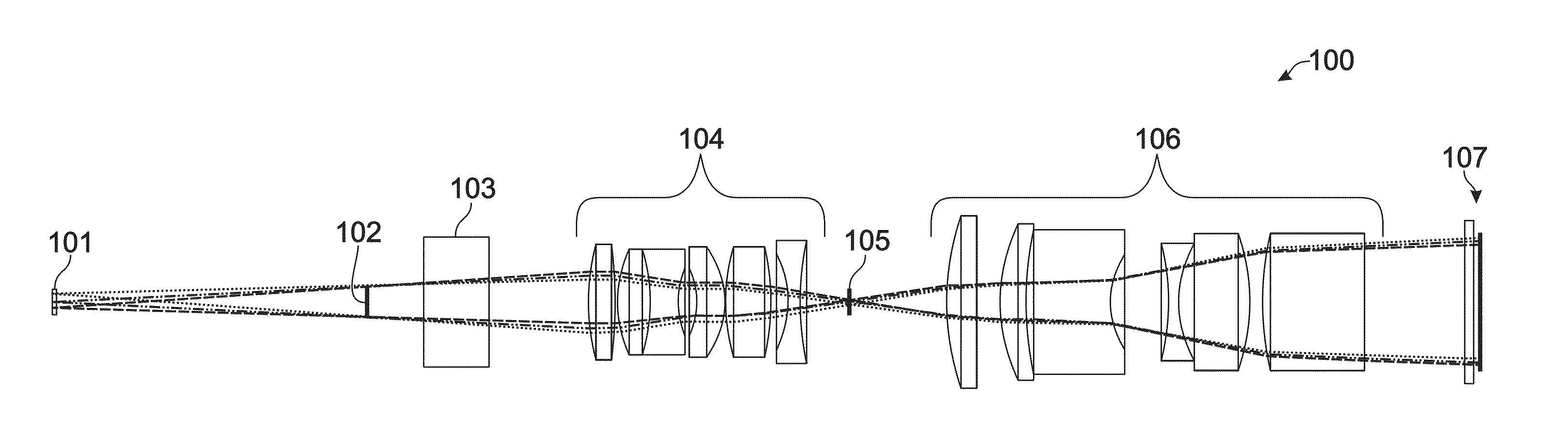
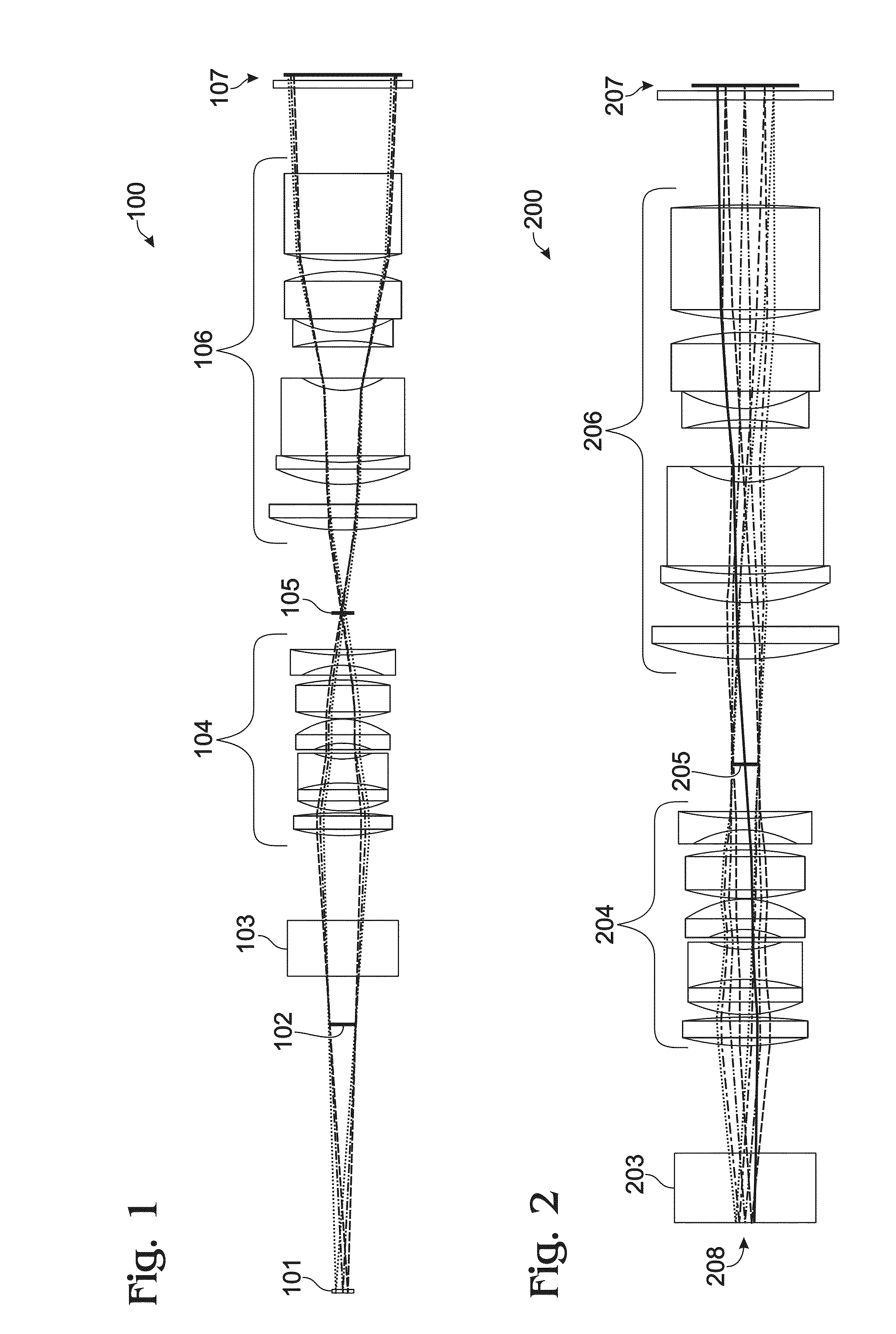
[0068]A high-brightness multicolor LED (red-green-blue-white) was placed below a channel in a microfluidic device and a digital color camera with two lenses was placed above the channel (FIG. 1). The multicolor LED can be conveniently customized to have light colors that closely match the color filters on the pixels of the image sensor. The multicolor LED also simplifies image analysis by having the different color emitters very close together, resulting in a similar illumination of the subject by each different color. The focal lengths and positions of the lenses were chosen to create sharp images of droplets in the channel. A stop was placed above the LED to limit the emitted light from spreading out. A second stop was placed between the two lenses to improve the image quality on the camera by increasing the camera image's depth of field at the channel. On the lens closer to the microfluidic channel, the focus was set to form an image of the LED dies at the stop ...


PUM


Abstract

Systems and methods are provided for determining a velocity or an inflation rate of a droplet in a microfluidic channel. The droplet is exposed to two or more temporally separated flashes of light, each flash including light of one wavelength band, and imaged using a detector configured to distinguish light in the wavelength bands. Two or more images of the droplet are acquired, each corresponding to one of the flashes, and all within a single video frame or photographic exposure. The images can be processed separately and the position or size of the droplet in each image is calculated. A velocity or inflation rate is then determined by dividing the change in position or size by the amount of time allowed to pass between the flashes.

Description

CROSS-REFERENCES TO RELATED APPLICATIONS[0001]This application claims the benefit of U.S. Provisional Patent Application No. 61 / 828,597, entitled “Low Cost Optical High Speed Discrete Measurement System” and filed on May 29, 2013, which is incorporated herein by reference in its entirety.BACKGROUND OF THE INVENTION[0002]Microfluidic methods involve passing small volumes of fluid through microfabricated structures and manipulating these volumes to carry out biological or chemical reactions. To stage such reactions, samples, reactants, solvents, or other reagents can be encapsulated in discrete droplets having volumes on the order of nanoliters or less. A droplet is typically immersed in a carrier fluid from which it is phase-separated, and transported along with the carrier fluid through microfluidic channels. In sufficiently small channels, this transport occurs at low Reynolds number and exhibits laminar flow. Reactions can be facilitated by, for example, merging droplets (causing ...

Claims


Application Information

Patent Timeline
Patent Type & Authority Applications(United States)
IPC IPC(8): G01P3/38G01B11/14G01P5/00G01F1/7086
CPCG01P3/38G01B11/14G01P5/00G01P5/001G01F1/7086G01N15/0227G01N35/08G01N2015/1493G01N15/1459G01N15/1434G01N15/1463G01N2015/1075G01N15/1484B01L3/502715B01L3/502784B01L2200/143B01L2400/0487B01L2400/082G01F22/00G01P5/20
Inventor TRACY, DAVID H.WEBER, AARONSTOKES, PETER
Owner BIO RAD LAB INC
Why Eureka
Try Eureka