Method of coating a substrate with a catalyst component

a technology of catalyst components and substrates, applied in the direction of physical/chemical process catalysts, separation processes, machines/engines, etc., to achieve excellent profile control and control of the dose length

Active Publication Date: 2014-12-04
JOHNSON MATTHEY PLC
View PDF26 Cites 7 Cited by
  • Summary
  • Abstract
  • Description
  • Claims
  • Application Information

AI Technical Summary

Benefits of technology

[0007]The inventors have developed a method and apparatus for automatedly and accurately coating substrates with a liquid comprising a catalyst component. In particular, the method and apparatus can uniformly coat the walls of the channels of a substrate with the liquid to a pre-determined length with minimal variation between the coating lengths of the channels. The method of the invention also allows excellent profile control and control over the dose length.

Problems solved by technology
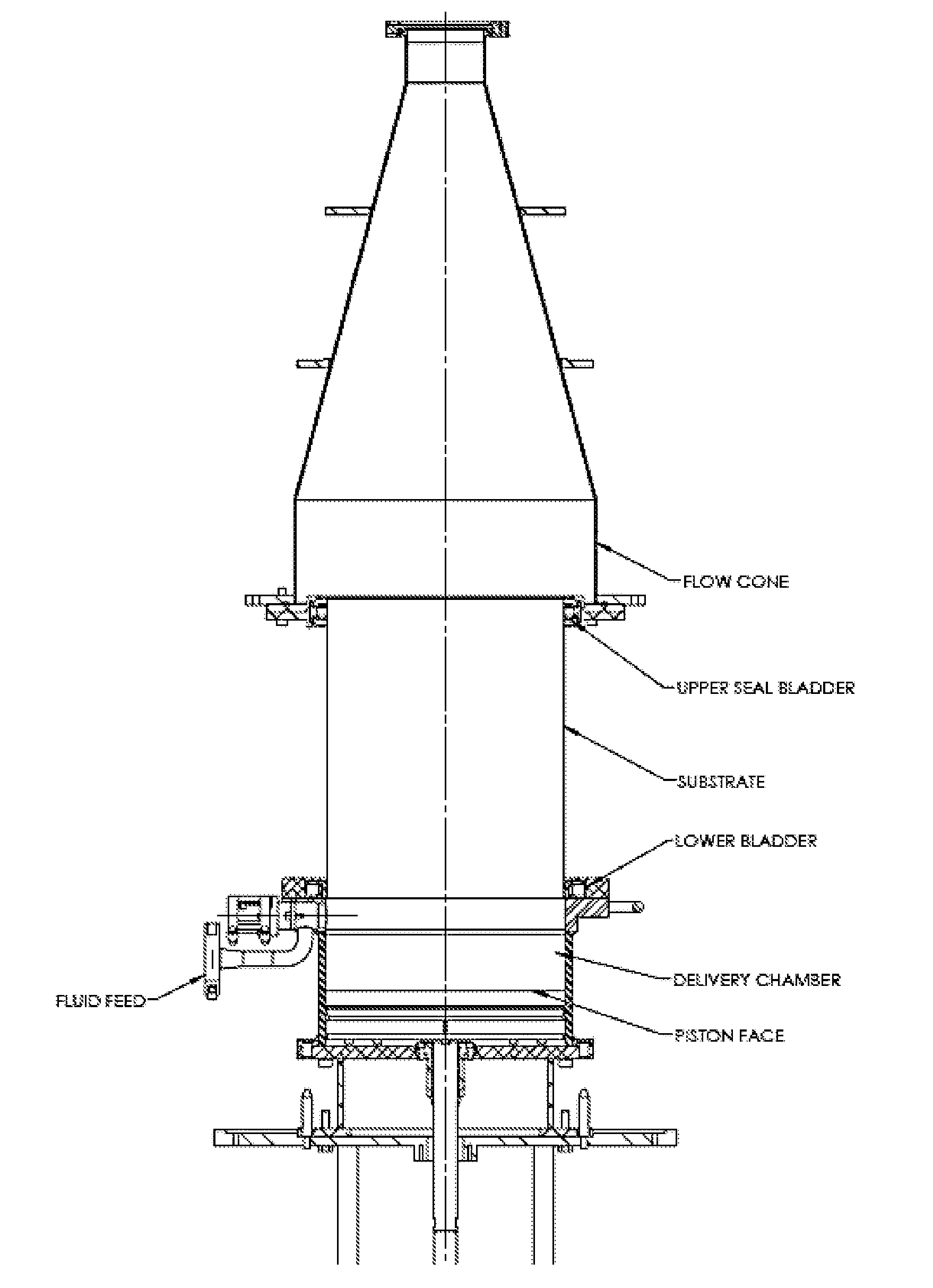
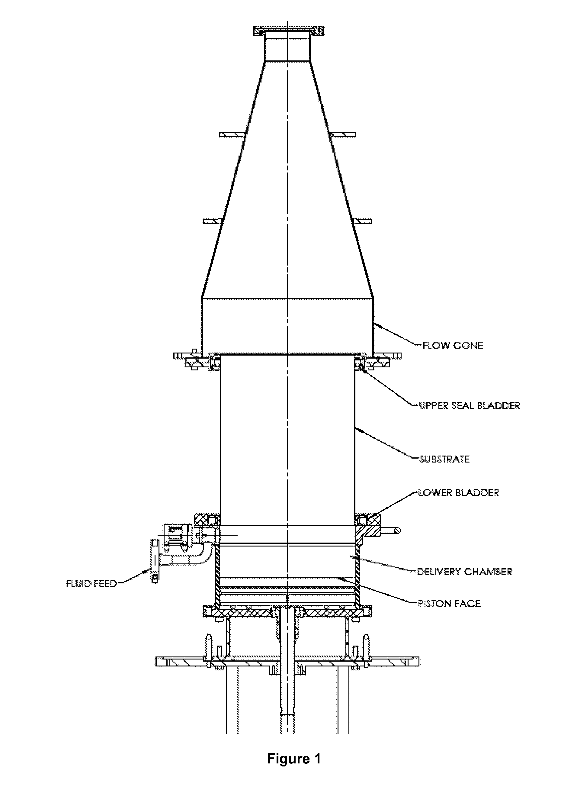
Problems can arise during the coating process that can depend on the properties of the substrate that is to be coated (e.g. size of the channels, the material from which the substrate is made and its porosity) and the properties (e.g. rheology) of the liquid that is used to form the coating.

Method used


Image

  • Method of coating a substrate with a catalyst component
  • Method of coating a substrate with a catalyst component
  • Method of coating a substrate with a catalyst component

Examples


example 1

[0150]Washcoat Preparation and Substrate

[0151]A conventional three-way catalyst washcoat was prepared for coating monolithic flow-through substrates. The viscosity of the washcoat was measured at 17° C. using a “Brookfield RV DVII+Extra Pro” viscometer with a SC4-27 spindle. The 1 rpm shear viscosity was approximately 26500 cP and the 50 rpm shear viscosity was 1500 cP.

[0152]A flow-through cordierite monolithic substrate having a height of 3.09″, a diameter of 4.16″ and 900 cells per cubic inch was coated. It was desired to coat a length of 55% of the axial length of the substrate. Set-up coating trials had shown that 163.3 g of washcoat would deliver the desired amount of washcoat and PGM onto the part. The mass of 163.3 g was a pre-determined amount (i.e. mass).

[0153]Coating Process

[0154]A pre-determined amount of washcoat was dispensed into the coating rig for subsequent monolith coating using a volumetric piston delivery system. The pre-determined amount of washcoat was a pre-de...

example 2

[0162]Washcoat Preparation and Substrate

[0163]A conventional three-way catalyst washcoat was prepared for coating monolithic flow-through substrates. The viscosity of the washcoat was measured at 17° C. using a “Brookfield RV DVII+Extra Pro” viscometer with a SC4-27 spindle. The 1 rpm shear viscosity was approximately 6500 cP and the 50 rpm shear viscosity was 285 cP.

[0164]A flow-through cordierite monolithic substrate having a height of 4.29″, a diameter of 4.16″ and 900 cells per cubic inch was coated. It was desired to coat a length of 50% of the axial length of the substrate. Set-up coating trials had shown that 190.0 g of washcoat would deliver the desired amount of washcoat and PGM onto the part. The mass of 190.0 g was a pre-determined amount (i.e. mass).

[0165]Coating Process

[0166]A pre-determined volume of washcoat was manually delivered to the apparatus (e.g. by hand) by pausing the normally automated sequence at the appropriate time, as explained below. The coating apparat...

example 3

[0171]Washcoat Preparation and Substrate

[0172]A conventional washcoat formulation for selective catalytic reduction (SCR) comprising a Cu zeolite was prepared. It was desired to coat a length of 60% of the axial length of a wall-flow filter with washcoat formulation.

[0173]Coating Processes

[0174]A wall-flow filter was coated with the washcoat formulation using the coating process of Example 1 (in accordance with the invention). The vacuum was triggered 0.5 seconds before introduction of the washcoat formulation through the lower end of the filter was complete (i.e. when the piston face touches the lower face of the filter).

[0175]As a comparison, the method was repeated using the same type of wall-flow filter and the same washcoat formulation. Instead of triggering the vacuum 0.5 seconds before the complete introduction of the washcoat formulation through the lower end of the filter, the vacuum was triggered 2 seconds after the introduction of the washcoat formulation through the lowe...


PUM

PropertyMeasurementUnit
viscositiesaaaaaaaaaa
lengthsaaaaaaaaaa

Abstract

A method of coating a substrate with a liquid comprising a catalyst component, which substrate comprises a plurality of channels, wherein the method comprises:
  • (a) holding the substrate vertically;
  • (b) introducing the liquid into the substrate through the open ends of the channels at a lower end of the substrate; and
  • (c) after the lower end of the substrate has been part-filled with the liquid, applying a vacuum to the open ends of the channels at the upper end of the substrate while introducing the liquid into the substrate.

Description

CROSS REFERENCE TO RELATED APPLICATIONS[0001]This application claims priority benefit to U.S. Provisional Patent Application No. 61 / 830,233 filed on Jun. 3, 2013, and to Great Britain Patent Application No. 1311615.7 filed on Jun. 28, 2013, all of which are incorporated herein by reference.FIELD OF THE INVENTION[0002]The invention relates to a method of coating a substrate with a liquid comprising a catalyst component. The coated substrate is for use in an emissions control device for treating or removing pollutants from an exhaust gas produced by an internal combustion engine. The invention further relates to an apparatus for coating a substrate with a liquid comprising a catalyst component.[0003]BACKGROUND TO THE INVENTION[0004]Emissions control devices (e.g. catalysts, such as three-way catalysts or diesel oxidation catalysts) for treating the exhaust gas of an internal combustion engine in both mobile and stationary applications typically include a substrate (e.g. a honeycomb mo...

Claims


Application Information

Patent Timeline
Patent Type & Authority Applications(United States)
IPC IPC(8): B01J37/02B05D3/02B05C11/02B05C7/04B05C7/02B05D3/04B05D7/22
CPCB01J37/0215B05D3/0493B05D3/0254B05C11/02B05C7/04B05C7/02B05D7/22B01J35/04B01J37/0234B01D53/94B05D7/24F01N3/20B05C7/00B05D3/0245B05D2254/04B65D7/22B05C11/023B05C13/00
Inventor ROBERTS, DALE ALBERTBORTZ, ANDREW MICHAELTROLAND, DANIEL L.ROSE, RICHARD PETERFORTNER, R. BRADFORD
Owner JOHNSON MATTHEY PLC
Why Eureka
Try Eureka