Combined laryngo-tracheal anesthetic and stylet device

a combination, tracheal technology, applied in the direction of respirators, process and machine control, instruments, etc., can solve the problems of increasing increasing the risk of complications, so as to reduce the total time involved, avoid the effect of increasing the requisite skill and dexterity of operation, and eliminating the possibility of injury and stress on the patient from repeated procedures

Active Publication Date: 2014-12-11
GUIDANCE AIRWAY SOLUTIONS LLC
View PDF8 Cites 22 Cited by
  • Summary
  • Abstract
  • Description
  • Claims
  • Application Information

AI Technical Summary

Benefits of technology

[0014]Still another objection of the present invention is to provide an LTA device that can be used during ETT placement without increasing the requisite skill and dexterity of operation. A feature of the present invention is a physical activation means such as lever, trigger, button, or a nonphysical activation means (such as an audio or electronic cue) that causes anesthetic or other medicament to exit a reservoir, that physical activation means placed near the region of the device adapted to be grasped by the user's hand. An advantage of the invention is that the device allows the anesthesiologist to deliver doses of anesthetic during an intubation procedure without needing to change hand position.
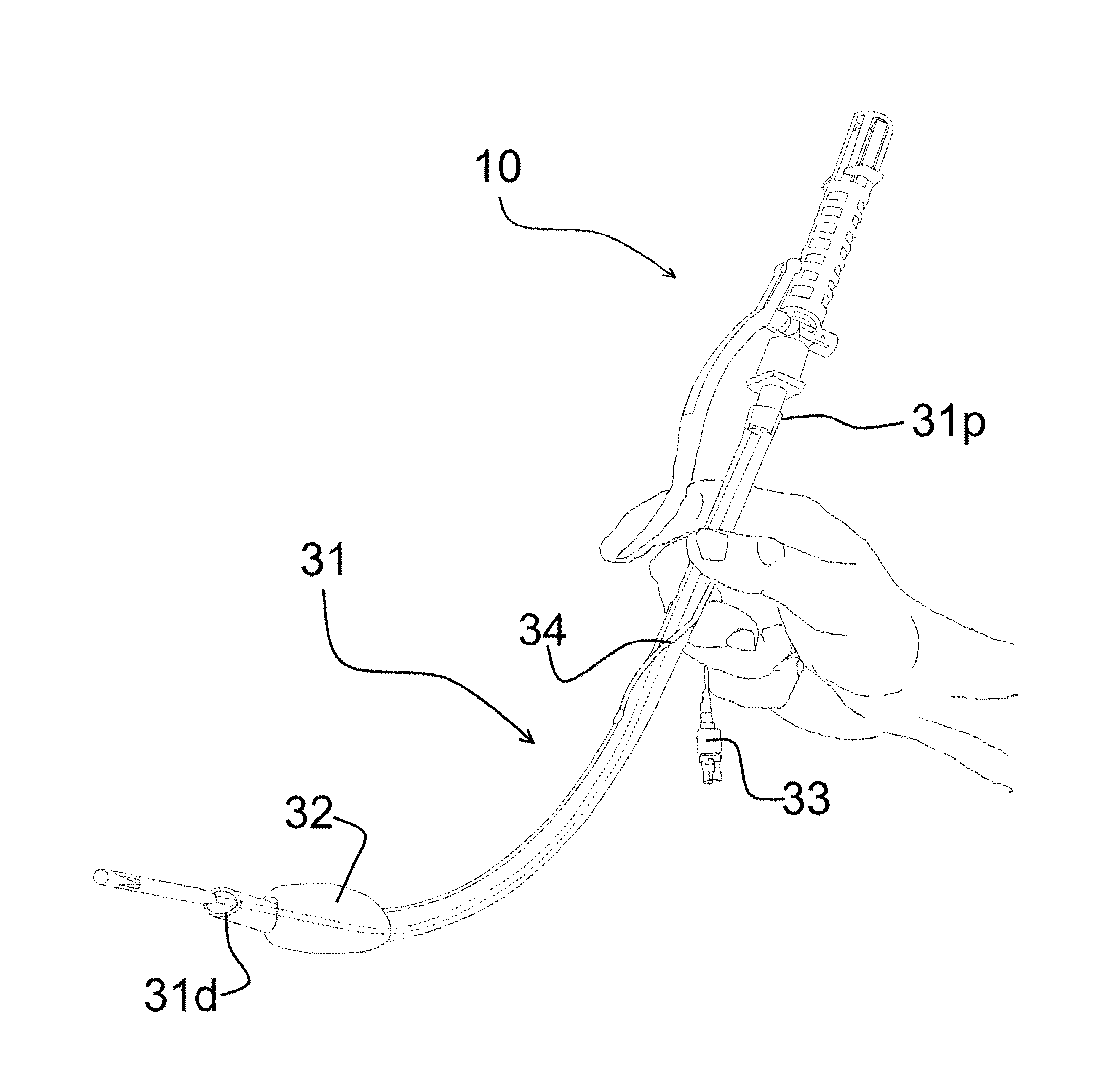
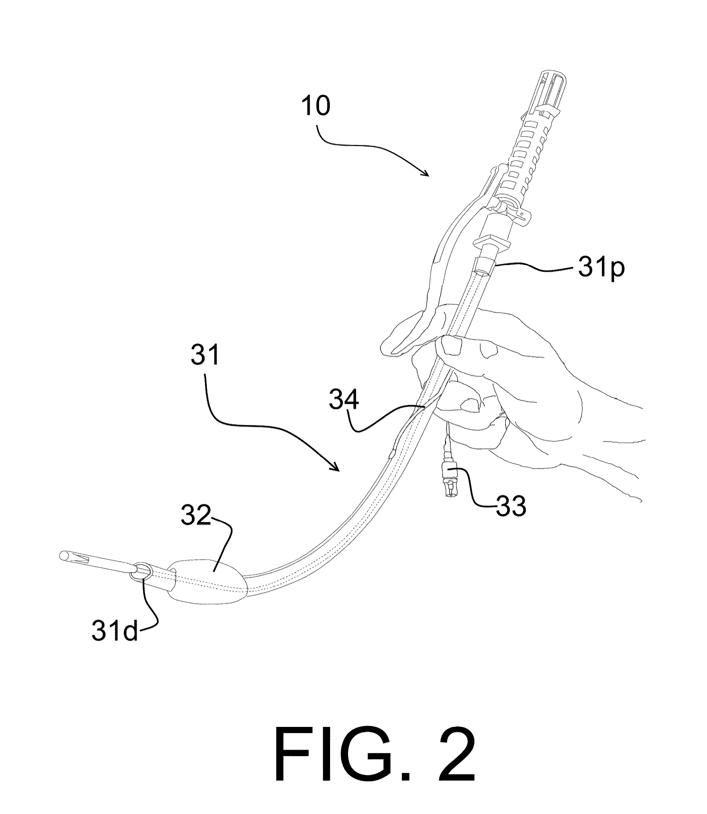
[0015]Still another object of the present invention is to provide a method to decrease the total time involved in performing a direct laryngoscopy. A feature of the present invention is utilizing an LTA device that functions as both a means for anesthetizing a patient's trachea and posterior pharynx and also as a stylet and introducer for placing an ETT. An advantage of the present invention is that separate direct laryngoscopies do not have to be performed for LTA and ETT placement; instead the method combines both functions such that they are performed simultaneously or within a few seconds, approximately one to 10 seconds, and preferably within about 3-6 seconds, and most preferably less than 5 seconds, from each other. A further advantage is that the potential injuries to and stress on the patient from repeated procedures are eliminated. A still further advantage is that the liability exposure for the anesthesiologist is consequently reduced.
[0016]A further object of the present invention is to provide an LTA device that is modular in design. A feature of some embodiments of the present invention is that the malleable conduit, dispenser, and anesthetic cartridges ca...

Problems solved by technology

These two or more discreet steps potentially distract the anesthetist who must first reach for the LTA device and then the ETT.
Also, the act of direct laryngoscopy places a great deal of stress on the patient.
Many patients, such as those with heart disease, do not tolerate these large swings in blood pressure and in heart rate which can occur with multiple acts of direct laryngoscopy.
Additionally, prolonged direct laryngoscopy creates increased risks for the patient.
Prolonging direct laryngoscopy causes increased edema, tissue trauma, bleeding, and secretions, which all impair the view of the vocal cords by the time the ETT is to be placed.
During this time period, the trachea is unprotected and the risk of aspiration is increased.
Also, on occasion the stimulation caused by LTA placement in an incompletely paralyzed patient may...

Method used


Image

  • Combined laryngo-tracheal anesthetic and stylet device
  • Combined laryngo-tracheal anesthetic and stylet device
  • Combined laryngo-tracheal anesthetic and stylet device

Examples


vial embodiment

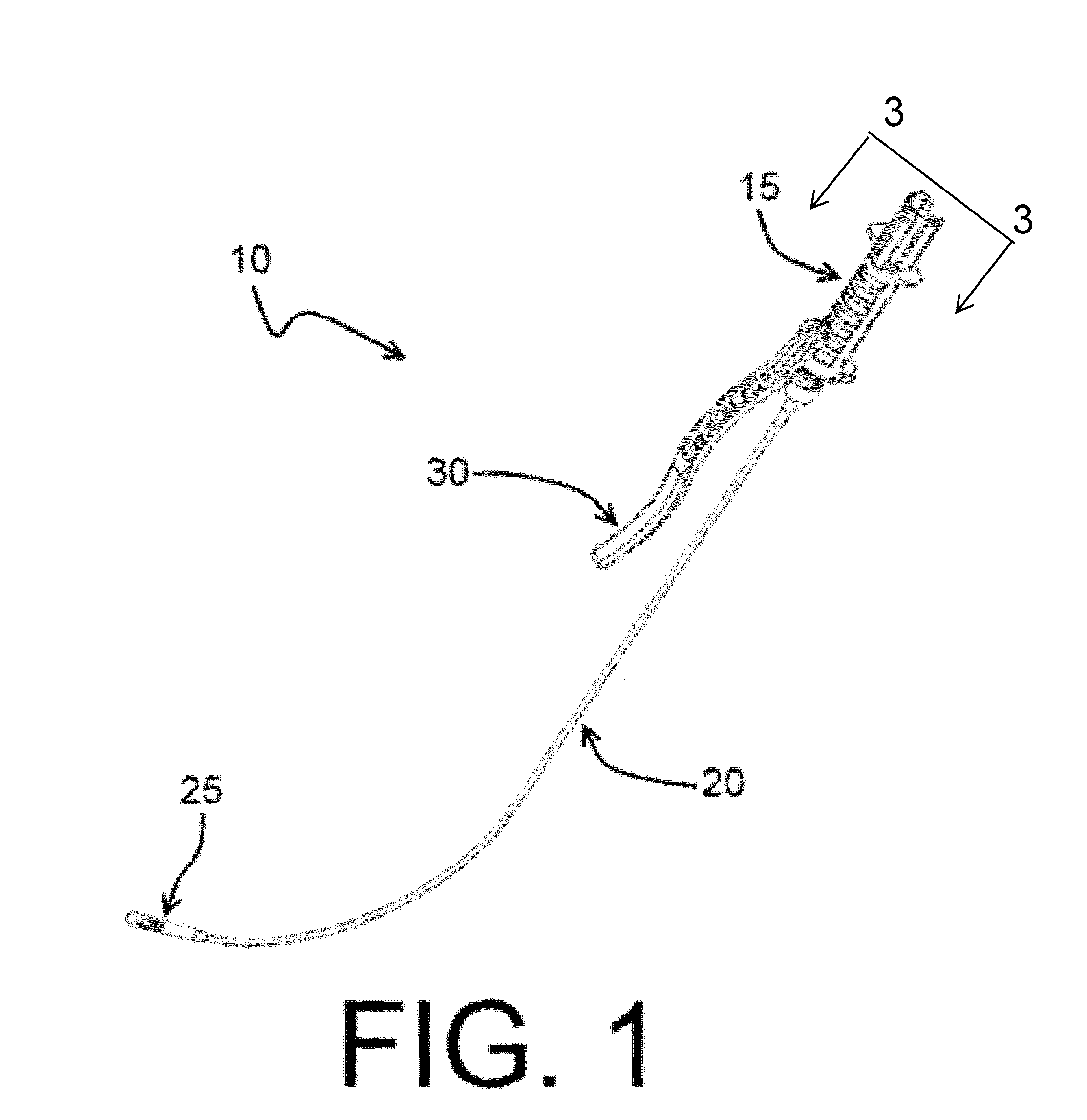
[0047]The dispenser 15 comes in a variety of embodiments. In each embodiment, the dispenser 15 is adapted to receive a cartridge or ampule of anesthetic. The dispenser 15 releases the contents of the cartridge for dispersion through the conduit 20 and out the nozzle 25 when actuated by the actuation means 30. However, the means for pressurizing the contents and the actuation means varies between the following embodiments.

[0048]In a primary embodiment that can be seen in FIG. 3, the dispenser 15 is comprised of a housing 35 defined by a first (or proximal) end 40, a second end 45, and a longitudinally extending perimeter wall 50. Towards the second end 45 is a flat substrate 55. Extending proximally from the flat substrate 55 is a piston 60. The piston can be spring loaded or hydraulically-, pneumatically-, or electrically-actuated. Various embodiments of the piston are discussed in greater detail infra. In a preferred embodiment, the piston 60 is spring loaded. Extending coaxial wit...

embodiment

Syringe Embodiment

[0063]In a second embodiment of the present invention depicted in FIGS. 7A-7D, the dispenser 15 works in combination with a syringe 102. In some configurations of the second embodiment, a reservoir 100 is utilized to pressurize the fluid in the syringe 102. In other configurations, the syringe 102 is pressurized, either internally or externally, and connected directly to a pressure release valve 104 (as shown in FIG. 8A).

[0064]In configurations using a reservoir 100, the reservoir 100 is adapted to receive the syringe of anesthetic as depicted in FIG. 7A such that the reservoir is positioned between the syringe and the stylet 20. The reservoir defines a cavity which is isolated from the ambient environment. The syringe 102 is a typical one in that it comprises a barrel 105, a plunger 110 slidably received by one end of the barrel, and a tip 115 positioned at a second end of the barrel. Some syringe embodiments also feature finger tabs 117, which provide a means to ...


PUM


Abstract

A laryngo-tracheal anesthetic device is provided, said device comprising a malleable conduit with a first end and a second end, wherein the second end is designed to enter a patient, a device for pressurizing anesthetic, wherein the device is adapted to receive a cartridge of anesthetic, a substrate actuated by a finger of a user for releasing anesthetic from the reservoir into the malleable tube; and a nozzle at the second end of the malleable tube.

Description

PRIORITY[0001]This utility application claims the benefit of U.S. Provisional Patent Application No. 61 / 832,979, filed on Jun. 10, 2013, the entirety of which is incorporated by reference.BACKGROUND OF THE INVENTION[0002]1. Field of the Invention[0003]The present invention relates to a method and device for anesthetizing and intubating, and more particularly, the present invention relates to a method and device for anesthetizing and intubating a patient with a single hand movement.[0004]2. Background of the Invention[0005]Laryngo-tracheal anesthesia (LTA) is an important component of the anesthetic plan for general anesthesia during surgery. LTA blunts airway reflexes and discomfort involved in the manipulation of the airway for surgery and facilitates placement and maintenance of an endotracheal tube (ETT). Of the approximately 15 million general anesthetic procedures performed each year that require an ETT, about one third will require the use of LTA.[0006]Often laryngo-tracheal a...

Claims


Application Information

Patent Timeline
IPC IPC(8): A61M16/04A61M11/00A61M5/168A61M5/145A61M19/00A61M5/42
CPCA61M16/0463A61M16/0488A61M19/00A61M11/007A61M5/16881A61M5/145A61M5/422A61B1/267A61M16/04A61M16/0484A61M2205/586A61M2206/14A61M16/0486A61M15/009A61M16/0404A61M2205/3375A61M39/24A61M2205/3592
Inventor HERSKOVIC, JOSHUA J.
Owner GUIDANCE AIRWAY SOLUTIONS LLC
Why Eureka
Try Eureka