Battery System for a Power Tool, As Well As Battery Holder Therefor, Charger, and Charging System

a battery system and power tool technology, applied in the field of power tool battery system, can solve the problems of difficult identification, difficult expansion or scaling, and sudden shutting or shutting of particular battery packs, and achieve the effect of easy expansion or scaling

Active Publication Date: 2014-12-11
MAKITA CORP
View PDF5 Cites 68 Cited by
  • Summary
  • Abstract
  • Description
  • Claims
  • Application Information

AI Technical Summary

Benefits of technology

[0010]According to the battery system described above, the user can simultaneously attach two or more battery packs to the charger using one or more of the battery holders. After charging, the user can simultaneously detach the battery packs, which are attached to one battery holder, from the charger simply by detaching the battery holder from the charger. Thereby, the plurality of battery packs can be charged easily and conveniently. In addition, the battery holder is also advantageous for storing and / or carrying two or more of battery packs. By attaching the plurality of battery packs to the battery holder, it is possible to efficiently and conveniently organize and store the plurality of battery packs and, in addition, to easily carry them.
[0011]In another aspect of the present teachings, it is noted that some users may prefer to interchangeably use two or more battery packs with a single power tool. However, in this case, it becomes necessary to appropriately manage each individual battery pack. For example, consider a case wherein some of the battery packs are used frequently while some are not used all that much. In this case, the frequently-used battery packs will deteriorate more quickly than the battery packs that are less frequently used and the less-frequently used battery packs may maintain the performance of substantially a new unit for a relatively long time. However, if the performance (e.g., the charge storing capacity) of the battery packs varies relative to each other, then the amount of work that the power tool can perform will vary with the selected battery pack. This can result in the problem that a particular battery pack may suddenly cut off or shut down (due to a lack of charge) during a power tool operation much earlier than the user had expected. What must be heeded here is that all of the battery packs have an identical or substantially similar external appearance. Consequently, it is difficult to identify, merely by the external appearance, which of the battery packs was recently charged and which was not and / or which of the battery pack(s) has (have) deteriorated overall more than one or more other battery packs.
[0012]Therefore, in another aspect of the present teachings, improved techniques are disclosed that enable a user to more easily manage a plurality of battery packs.
[0028]The greater the number of battery interfaces that the charger has, the greater the number of battery packs that can be charged simultaneously. Nevertheless, each user may possess a different number of battery packs, such that a user who possesses a large number of battery packs will require a correspondingly large number of battery interfaces if the user wishes to be able to simultaneously charge most or all of the battery packs in his / her possession. On the other hand, if the user possesses only two or three battery packs, two or three battery interfaces would be sufficient. Taking this point into consideration, the charger preferably has a structure that enables a desired or optimal number of battery interfaces to be provided based upon the user's particular circumstances (i.e. the number of battery packs in his / her possession). That is, the charger's charging capacity preferably is easily expandable or scalable to adjust to the user's needs.

Problems solved by technology

In this case, the frequently-used battery packs will deteriorate more quickly than the battery packs that are less frequently used and the less-frequently used battery packs may maintain the performance of substantially a new unit for a relatively long time.
This can result in the problem that a particular battery pack may suddenly cut off or shut down (due to a lack of charge) during a power tool operation much earlier than the user had expected.
Consequently, it is difficult to identify, merely by the external appearance, which of the battery packs was recently charged and which was not and / or which of the battery pack(s) has (have) deteriorated overall more than one or more other battery packs.

Method used


Image

  • Battery System for a Power Tool, As Well As Battery Holder Therefor, Charger, and Charging System
  • Battery System for a Power Tool, As Well As Battery Holder Therefor, Charger, and Charging System
  • Battery System for a Power Tool, As Well As Battery Holder Therefor, Charger, and Charging System

Examples


first embodiment

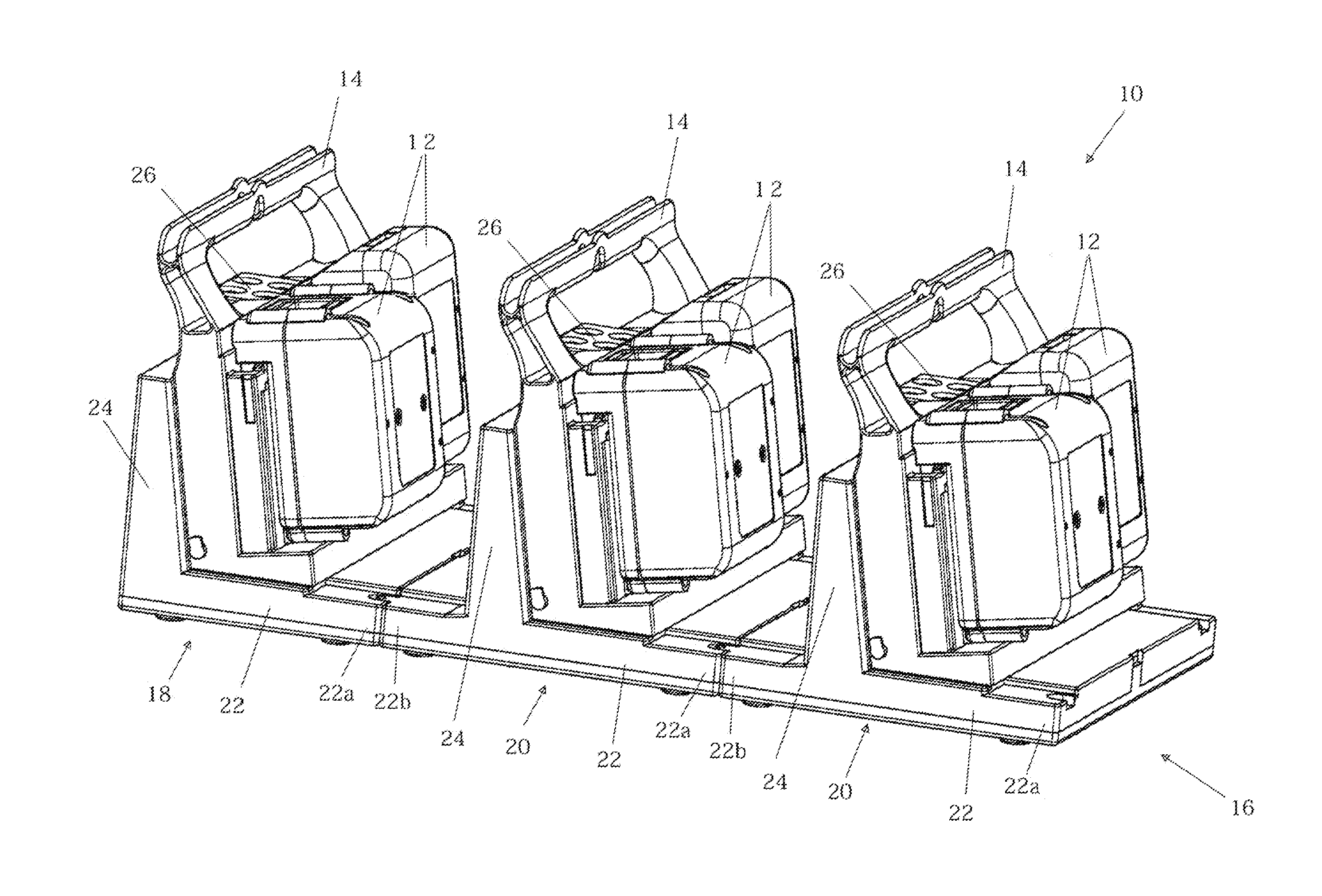
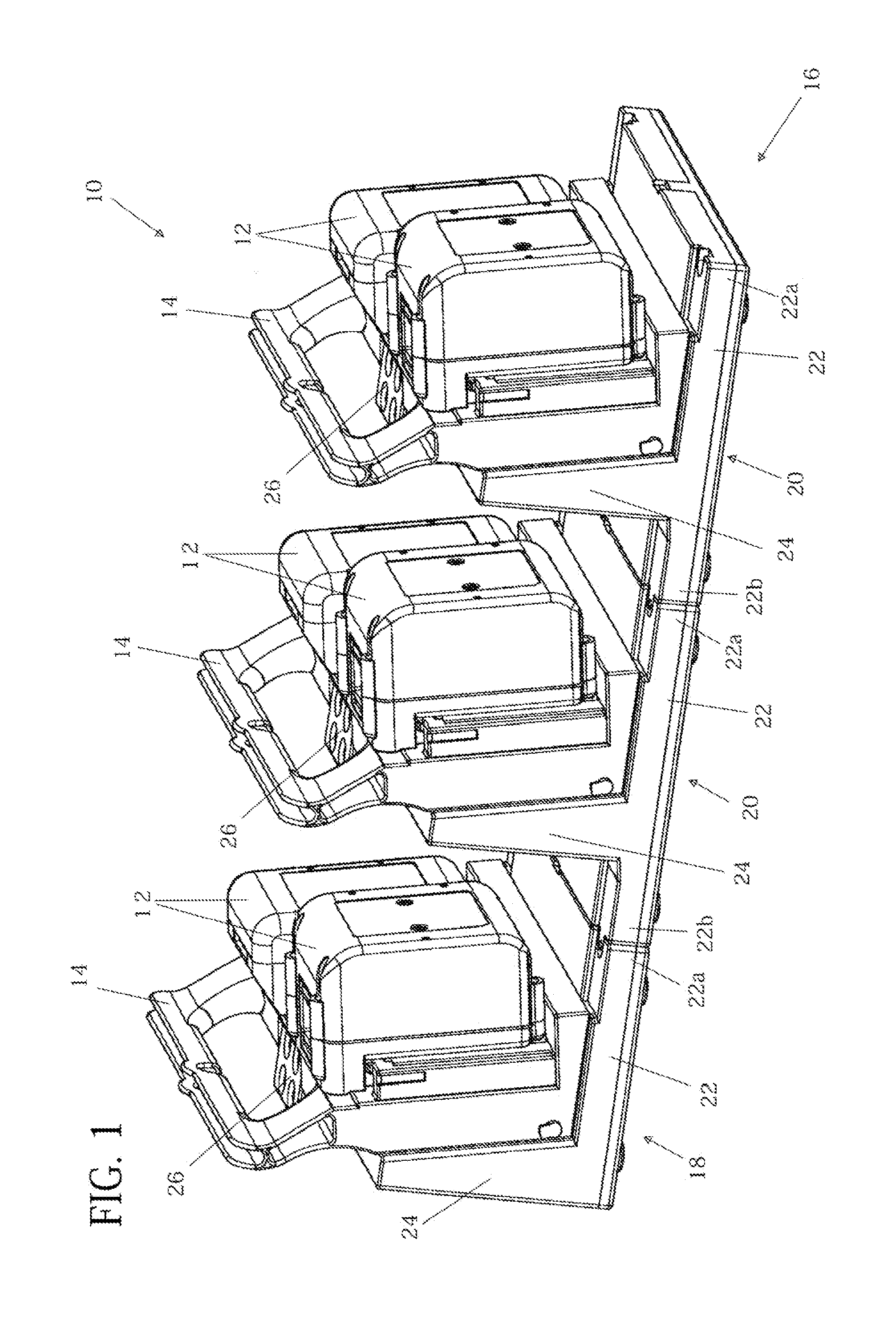
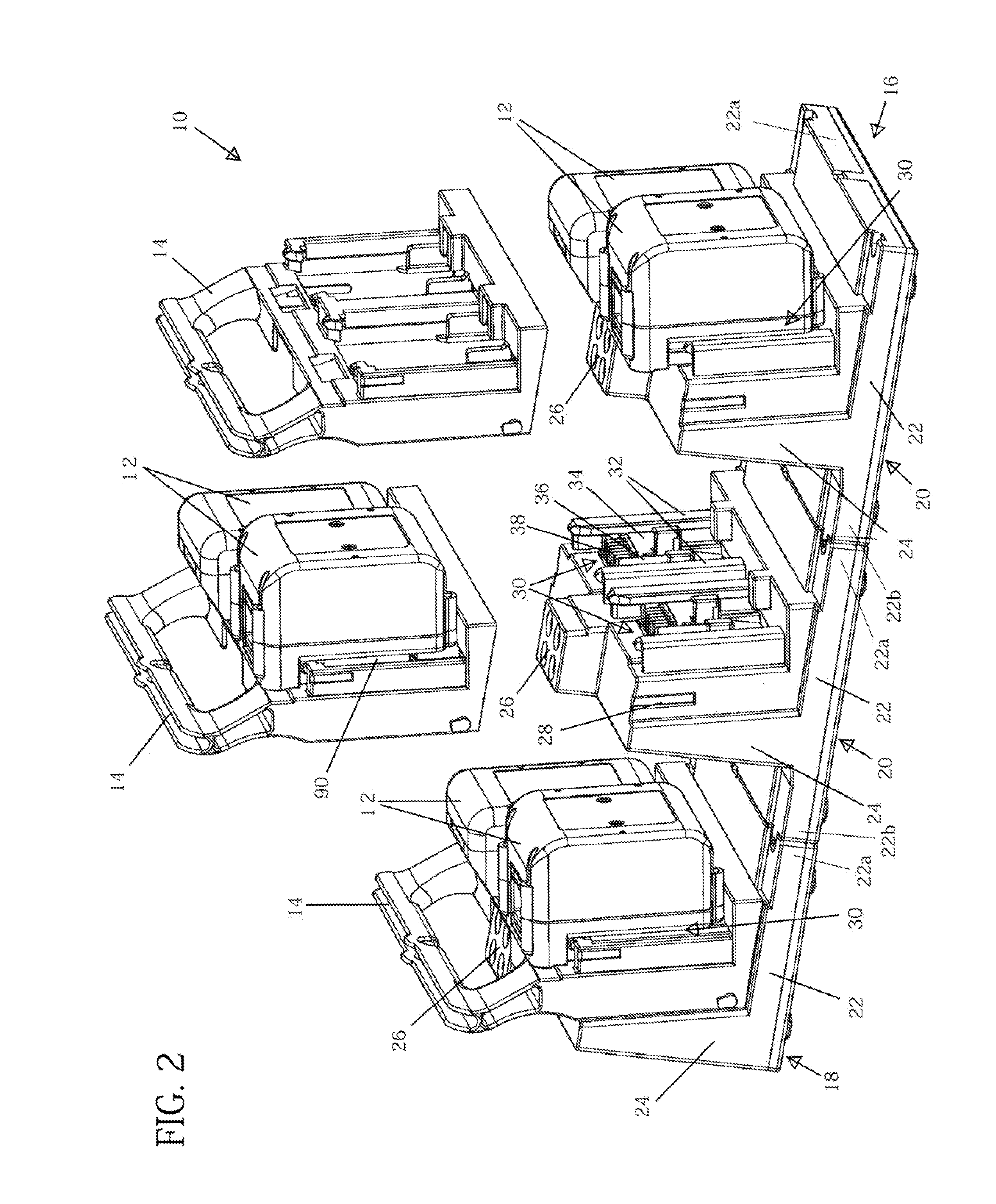
[0071]A battery system 10 of a first embodiment will now be explained. The battery system 10 is designed to supply electric current (power) to a power tool. As shown in FIG. 1 and FIG. 2, the battery system 10 preferably comprises a plurality of battery packs 12, a plurality of battery holders 14, and a charger 16.

[0072]The battery packs 12 serve as power supplies for the power tool. The battery packs 12 are configured such that they are capable of attaching to and detaching from the power tool in order to supply the stored electric power to the power tool. The battery packs 12 are charged by the charger 16. The plurality of battery packs 12 may be identical or may include two or more different types of battery packs, e.g., having different capacities, different rated (nominal) voltages, etc.

[0073]Each of the battery holders 14 is configured such that at least two of the battery packs 12 can be attached thereto and detached therefrom; in the present embodiment, two battery packs 12 ...

second embodiment

[0104]A charger 216 of a second embodiment will now be explained with reference to FIG. 16A, FIG. 16B, and FIG. 17. The charger 216 of the second embodiment is a modified example of the charger 16 explained in the first embodiment and can use the battery system 10 of the first embodiment. Constituent elements (components) in common with the charger 16 of the first embodiment are assigned identical reference numbers and thus, a repetition of the detailed explanation of their construction and functions may be omitted. In principle, with minor modifications, the charger 216 could also be implemented, e.g., with the electric circuit configuration of either FIG. 14B or 14C, the description of which is incorporated into the present embodiment.

[0105]The charger 216 comprises a plurality of the battery interfaces 30, e.g., three in the present embodiment. Each of the battery interfaces 30 is configured such that one battery pack 12 can be attached thereto and detached therefrom. Each of the...

third embodiment

[0108]A charger 316 of a third embodiment will now be explained, with reference to FIGS. 18-20. The charger 316 of the third embodiment is a modified example of the charger 16 that was explained in the first and second embodiments and can use the battery system 10 of the first embodiment. Constituent elements in common with the charger 16 of the first embodiment are assigned identical reference numbers and thus need not be explained in detail below. Again, in principle, with minor modifications, the charger 316 could also be implemented, e.g., with the electric circuit configuration of either FIG. 14B or 14C, the description of which is incorporated into the present embodiment.

[0109]The charger 316 comprises a main unit 318 (i.e., a master unit) and one or more tray units 320 (i.e., a slave unit). The main unit 318 is configured such that one tray unit 320 can be attached thereto and detached therefrom. Referring to FIG. 19, the main unit 318 comprises a main unit positive terminal ...


PUM


Abstract

A battery system for a power tool includes two or more battery packs (12), at least one battery holder (14) adapted to detachably engage two or more of the battery packs and a charger (16, 216, 316, 416) adapted to detachably engage the battery holder and to simultaneously electrically communicate with two or more of the battery packs while the at least one battery holder engages both the charger and the battery packs.

Description

CROSS-REFERENCE[0001]The present application claims priority to U.S. provisional patent application Ser. No. 61 / 581,943 filed on Dec. 30, 2011 and U.S. provisional patent application Ser. No. 61 / 702,559 filed on Sep. 18, 2012, the contents of both of which are incorporated fully herein.TECHNICAL FIELD[0002]The present teachings generally relate to a battery system for a power tool, as well as to a battery holder therefor, a charger, a charging system and a battery system containing the same.BACKGROUND ART[0003]A battery system for a power tool is disclosed in JP2002-238177A. This battery system comprises a plurality of battery packs and a charger for charging the plurality of battery packs. The charger comprises a plurality of battery interfaces, each battery interface accepting one of the battery packs, and thereby can charge the plurality of battery packs.SUMMARY[0004]According to the above-described known battery system, a user can simultaneously charge the plurality of battery p...

Claims


Application Information

Patent Timeline
Patent Type & Authority Applications(United States)
IPC IPC(8): H02J7/00H02J7/02
CPCH02J7/0044H02J7/025H02J7/0045H02J7/02B25H3/022H02J7/0013H02J50/80H02J2310/22H02J50/40H02J50/10H02J5/00H02J7/00034H02J7/00045
Inventor SUZUKI, HITOSHIITO, KOSUKENAITO, AKIRA
Owner MAKITA CORP
Why Eureka
Try Eureka