Color electro-optic displays

a display and electro-optic technology, applied in the field of electro-optic displays and materials, can solve the problems of affecting the display quality, and reducing so as to reduce the quality of the display

Active Publication Date: 2014-12-11
E INK CORPORATION
View PDF17 Cites 18 Cited by
  • Summary
  • Abstract
  • Description
  • Claims
  • Application Information

AI Technical Summary

Benefits of technology

[0041]It has now been found that the proper operation of rear CFA displays is greatly influenced by the electrical properties of the colored materials used in the CFA (e.g., dyes such as colored photoresists). If the electrical resistivity (sometimes also referred to as the specific electrical resistance, which is different from the electrical resistance of a structure) of the colored material is too high, electrical communication between the electrodes might be impeded to the extent that the display will not switch correctly, reducing the quality of the display or even rendering it inoperable.

Problems solved by technology

If the electrical resistivity (sometimes also referred to as the specific electrical resistance, which is different from the electrical resistance of a structure) of the colored material is too high, electrical communication between the electrodes might be impeded to the extent that the display will not switch correctly, reducing the quality of the display or even rendering it inoperable.

Method used


Image

  • Color electro-optic displays
  • Color electro-optic displays
  • Color electro-optic displays

Examples


Embodiment Construction

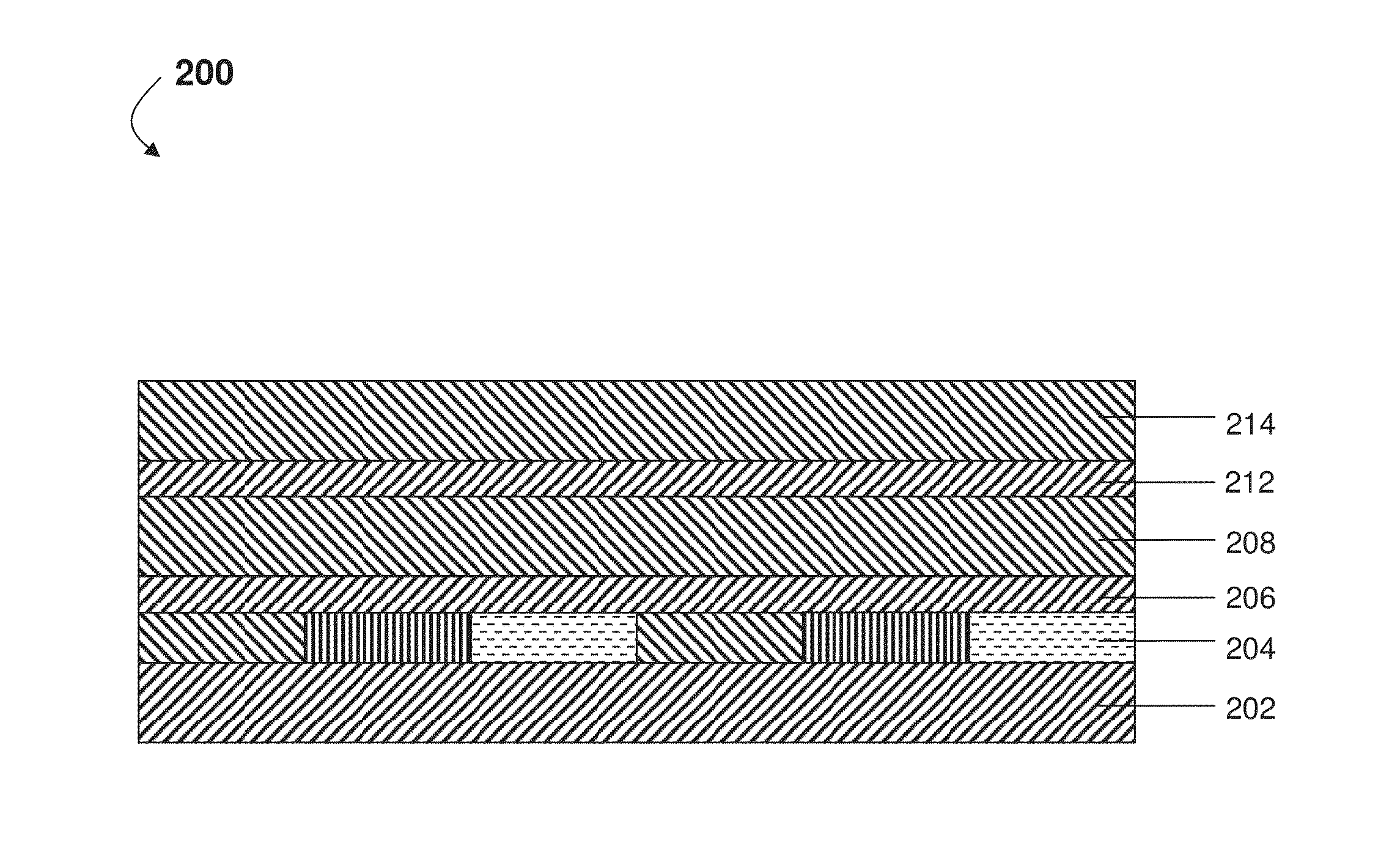
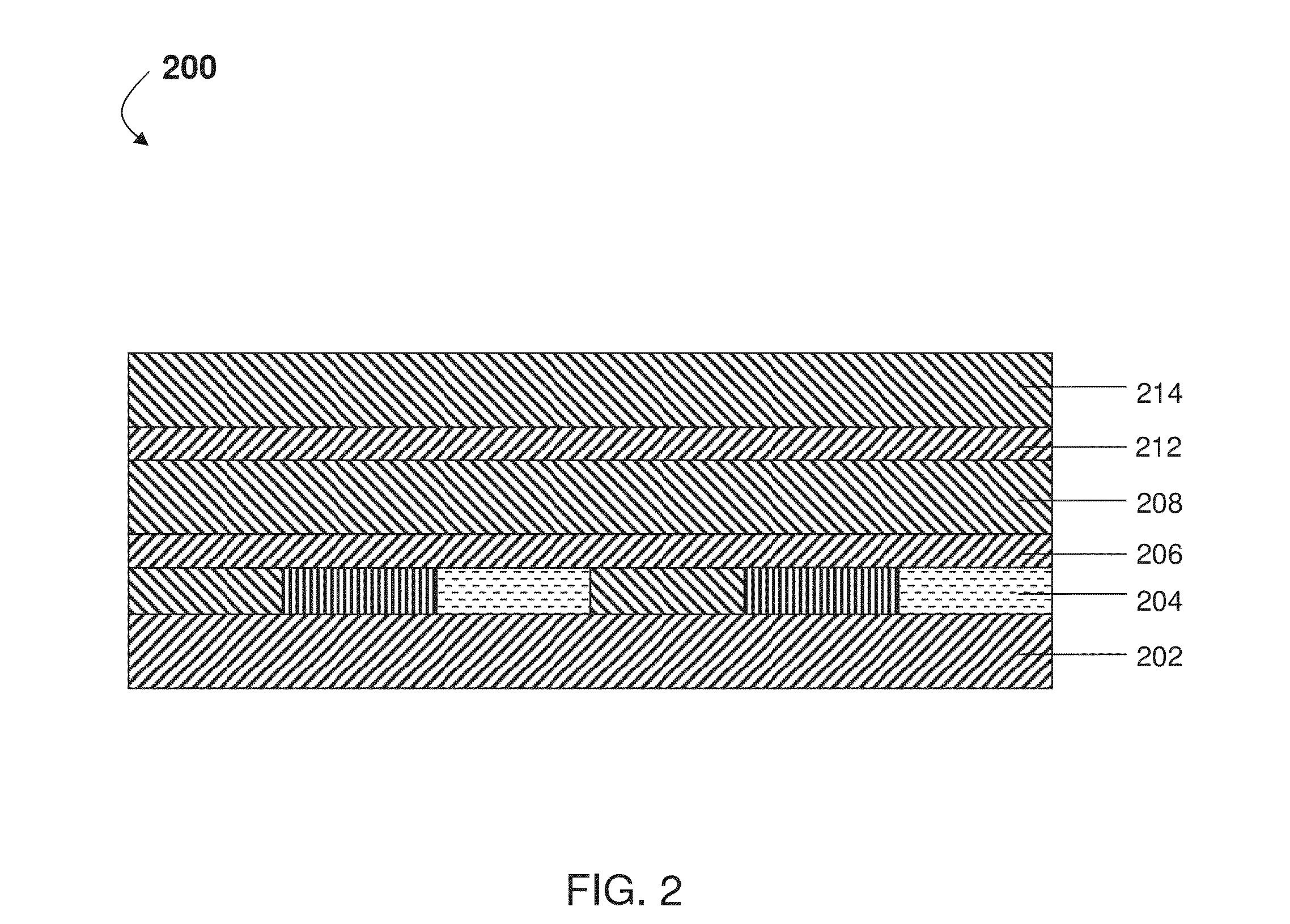
[0058]As previously mentioned, this invention provides rear CFA displays in which the colored materials have electrical properties that allow for proper operation of the display. Also this invention provides displays comprising sub-pixels in which the colored materials are spatially distributed such that proper electrical operation is maintained while producing suitable color.

[0059]The term “colored material is used herein to mean a material present within a sub-pixel in order to provide a color used to produce a color image. Exemplary colored materials include, but are not limited to, dyes, colored photoresists, and the like.

[0060]In one aspect, a color filter array comprising layers of material with controlled electrical properties and / or thicknesses is provided. In some embodiments, the color filter array display comprises a colored material with a relatively low electrical resistivity. The use of colored materials with relatively low electrical resistivities allows for electrica...


PUM

PropertyMeasurementUnit
resistivityaaaaaaaaaa

Abstract

A color filter array or a backplane for a color display has first and second areas with substantially different optical properties. The invention also provides a color filter with a low resistivity. The invention further provides a color display utilizing fluorescent or phosphorescent material.

Description

REFERENCE TO RELATED APPLICATIONS[0001]This application claims benefit of copending Provisional Application Ser. No. 61 / 761,333, filed Feb. 6, 2013, and of copending Provisional Application Ser. No. 61 / 761,879, filed Feb. 7, 2013.[0002]The entire contents of these copending applications and of all other U.S. patents and published and copending applications mentioned below, are herein incorporated by reference.BACKGROUND OF INVENTION[0003]This invention relates to electro-optic displays and materials for use in such displays. More specifically, in one aspect, this invention relates to color electro-optic displays utilizing rear color filters, and in another aspect, this invention relates to electro-optic displays in which fluorescent or phosphorescent materials are used to enhance the amount of light reflected from the display in certain states of the display.[0004]The term “electro-optic”, as applied to a material or a display, is used herein in its conventional meaning in the imagi...

Claims


Application Information

Patent Timeline
Patent Type & Authority Applications(United States)
IPC IPC(8): G09G3/20G09G3/30G02F1/167
CPCG09G3/2003G09G2310/0272G09G2310/0235G09G3/30G02F1/133514G02F1/167
Inventor PAOLINI, JR., RICHARD J.TELFER, STEPHEN J.
Owner E INK CORPORATION
Why Eureka
Try Eureka