
Method and device for determining a charge state of an electric energy store

a technology of electrical energy store and charge state, which is applied in the direction of measurement devices, instruments, computing, etc., can solve the problems of unambiguous relationship, energy loss from the battery, and change in the total capacity of the rechargeable battery

Inactive Publication Date: 2014-12-11
SIEMENS AG
View PDF11 Cites 4 Cited by
  • Summary
  • Abstract
  • Description
  • Claims
  • Application Information

AI Technical Summary

Benefits of technology

The patent relates to a method for determining the state of charge of a battery and preventing damage to the battery by avoiding excessive discharging or overcharging. This method improves the safety and durability of batteries with flat voltage characteristic curves, such as lithium-metal-phosphate cells, by detecting abnormal operating voltages and conserving the battery's energy. The technical effects of this patent are improved safety and durability of batteries and the prevention of damage caused by excessive charging or discharging.

Problems solved by technology

In addition, this relationship is unambiguous since charge and discharge have the same curve profile.
However, owing to temporal and / or load-related aging, the total capacity of the rechargeable battery changes.
Likewise, energy is lost from the battery over time owing to self-discharge.
During use of rechargeable batteries in “float operation”, that is to say without fully completed charge and discharge cycles or without a regular charge and / or discharge of the rechargeable batteries, said calibration point is not reached in some cases for a relatively long time.
Likewise, in the case of an expensive, highly precise current measurement, the measurement of the no-load voltage and hence the correlation of the no-load voltage to the state of charge physically quickly reaches the limits of measuring electronics or the electrochemistry predefined by the cell chemistry.

Method used


Image

  • Method and device for determining a charge state of an electric energy store
  • Method and device for determining a charge state of an electric energy store
  • Method and device for determining a charge state of an electric energy store

Examples


Embodiment Construction

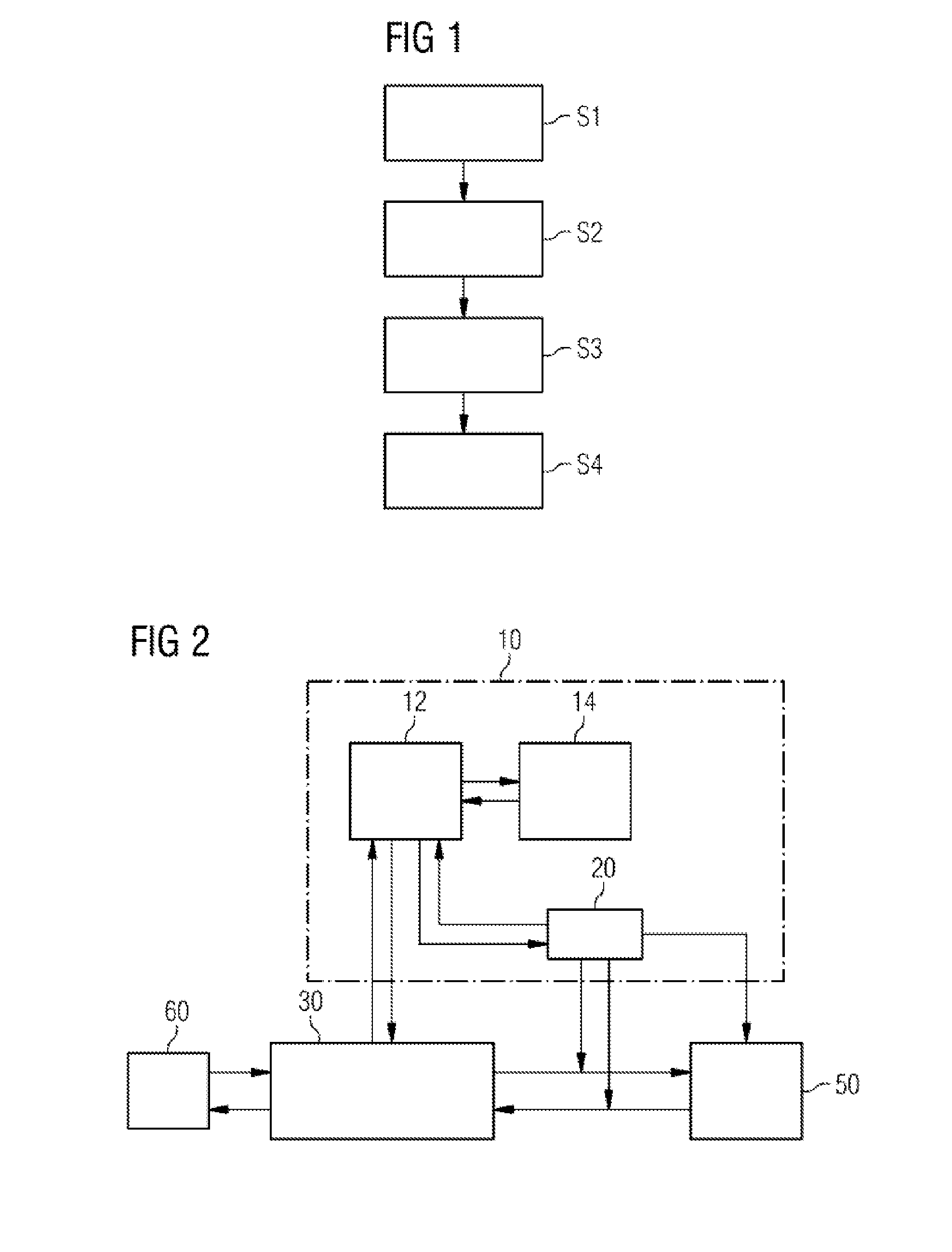
[0050]FIG. 1 shows an illustration of a flow chart of a possible embodiment of the method according to the invention.

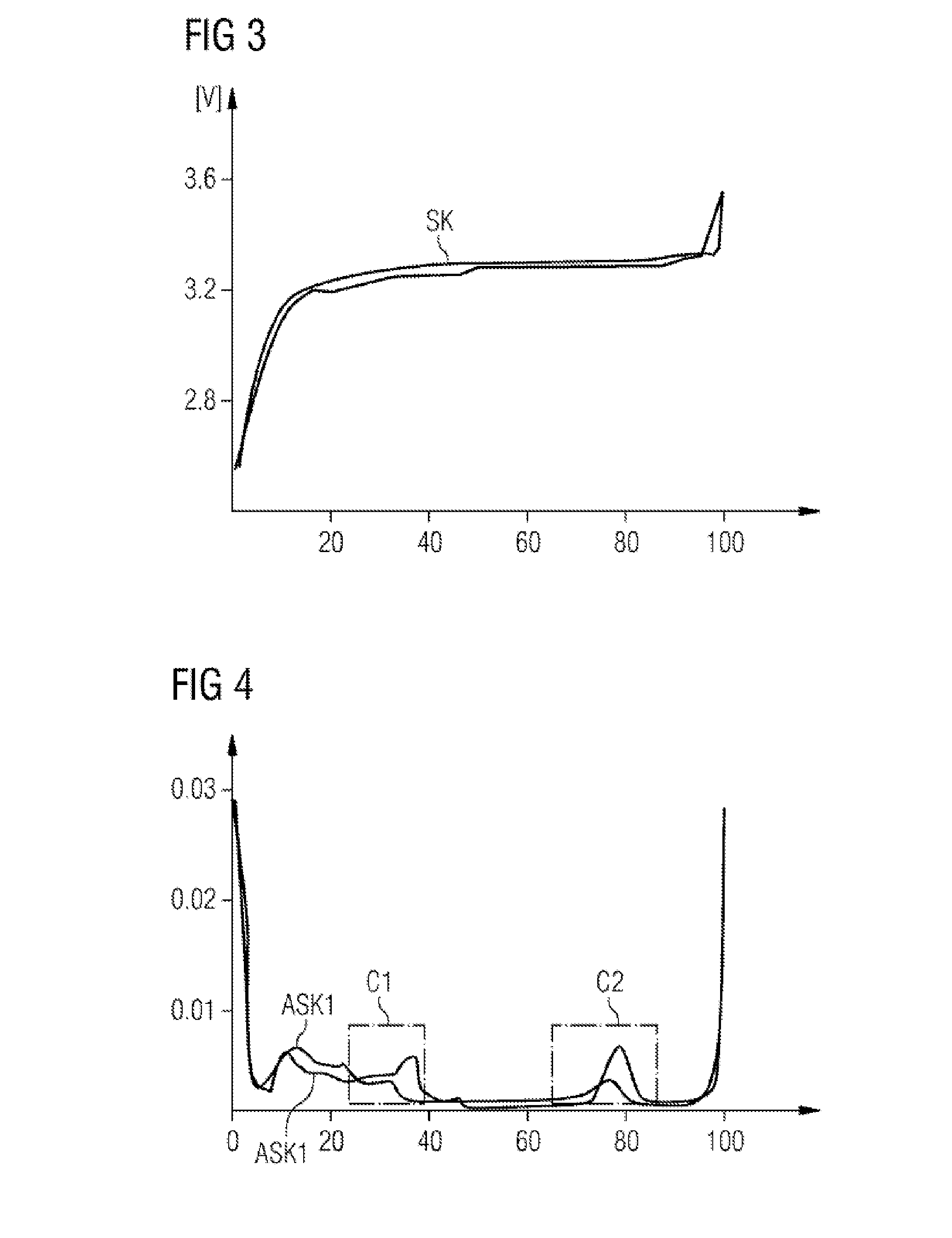
[0051]In a first step of the method, a voltage of the electrical energy store 50 is measured S1, as a voltage characteristic curve SK, as a function of an amount of charge drawn from or supplied to the electrical energy store 50 and a virtual no-load voltage characteristic curve is calculated from the measured voltage, taking into account at least one operating parameter of the electrical energy store 50.

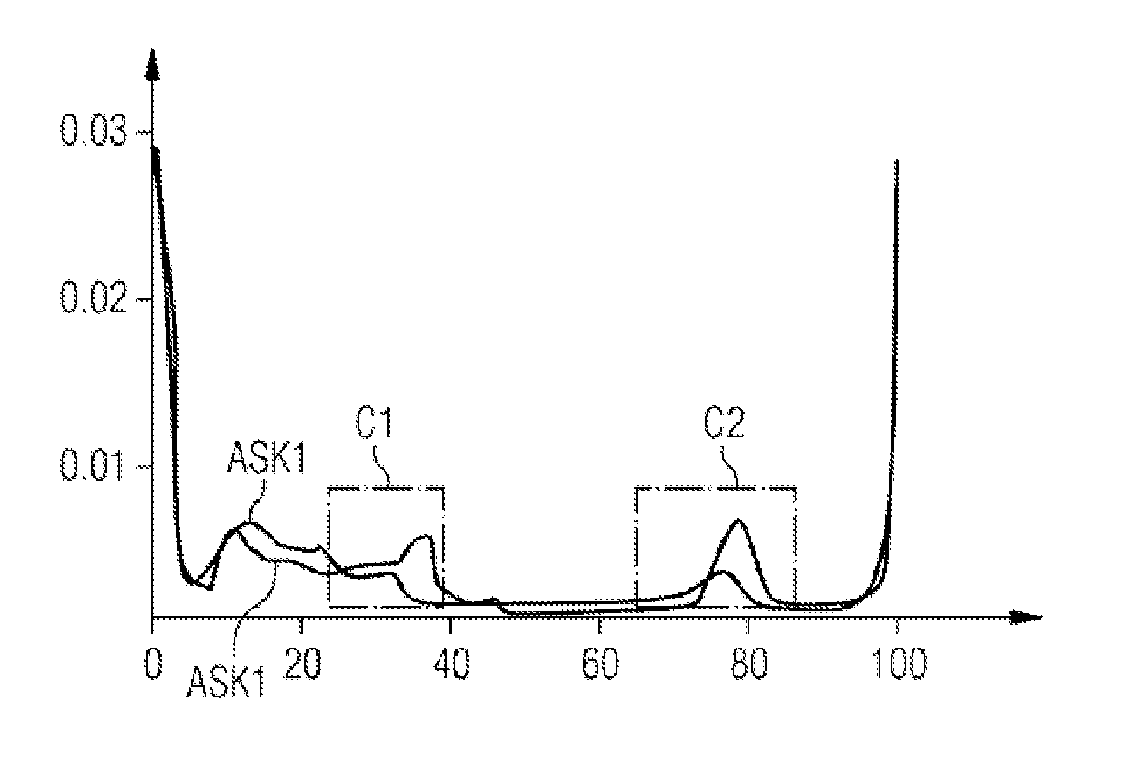
[0052]In a second step S2 of the method, a first derivative ASK1 and / or a second derivative ASK2 of the virtual no-load voltage characteristic curve according to the amount of charge drawn from or supplied to the electrical energy store 50 is calculated S2.

[0053]By way of example, the hysteresis behavior of the electrical energy store 50 is taken into account in the case of calculating the virtual no-load voltage characteristic curve. The virtual no-load voltage obtai...


PUM


Abstract

A method for determining a charge state of an electric energy store, having the following steps: measuring a voltage of the electric energy store on the basis of a charge quantity which is removed from or supplied to the electric energy store as a voltage characteristic curve and ascertaining a virtual open-circuit voltage characteristic curve from the measured voltage using at least one operating parameter of the electric energy store, ascertaining a first derivative and / or a second derivative of the virtual open-circuit voltage characteristic curve according to the charge quantity removed from or supplied to the electric energy store, detecting at least one characteristic of the first derivative and / or the second derivative of the virtual open-circuit voltage characteristic curve, and determining the charge state of the electric energy store using the detected at least one characteristic, is provided.

Description

CROSS-REFERENCE TO RELATED APPLICATIONS[0001]This application claims priority to PCT Application No. PCT / EP2012 / 076574, having a filing date of Dec. 21, 2012, based off of DE Application No. 102012200414.9, having a filing date of Jan. 12, 2012, the entire contents of which are hereby incorporated by reference.FIELD OF TECHNOLOGY[0002]The following relates to a method and a device for determining a state of charge of an electrical energy store.BACKGROUND[0003]DE 38 53 86 4 T2 describes a charging device for charging rechargeable batteries, comprising a means for supplying electrical charging energy to a rechargeable battery to quickly charge the rechargeable battery, comprising a means for capturing a voltage of the rechargeable battery, comprising a means for providing a preselected reference voltage and comprising a means for comparing the voltage of the battery with the preselected reference voltage.[0004]FIG. 6 shows an exemplary illustration of a graph with a discharge curve of...

Claims


Application Information

Patent Timeline
Patent Type & Authority Applications(United States)
IPC IPC(8): G01R31/36
CPCG01R31/3648G01R31/3665G01R31/362G01R31/3842G01R31/367G01R31/378G01R31/3835
Inventor HAHN, ALEXANDERRABBERS, JACOB JOHANWEYDANZ, WOLFGANGWOLFSCHMIDT, HOLGER
Owner SIEMENS AG
Learn More