Annular ring and non-pneumatic tire

a non-pneumatic tire and annular ring technology, applied in the field of non-pneumatic tires, can solve the problems of large contact area, low vertical stiffness, and high load capacity of pneumatic tires per unit mass, and achieve the effects of low friction, low friction, and high load capacity per unit mass

Active Publication Date: 2014-12-18
CAMOPLASY INC
View PDF13 Cites 77 Cited by
  • Summary
  • Abstract
  • Description
  • Claims
  • Application Information

AI Technical Summary

Problems solved by technology

Pneumatic tires offer high load capacity per unit mass, along with a large contact area and relatively low vertical stiffness.
However, pneumatic tires are also prone to flats.
Well known in the patent literature, non-pneumatic tires offer flat-free operation, yet generally contain some compromise.
Higher cost is often associated with non-pneumatic tires when complex assemblages of composite materials are used.
Related to this, production methodologies can be laborious.
High production costs could be involved.
Such a structure works acceptably well for very small tires and low loads; however, one skilled in the art of non-pneumatic structures can show that this technological approach would result in high tire mass for applications supporting higher loads in larger-scale applications.
However, at higher loads with larger tire dimensions, one skilled in the art of non-pneumatic tire design can show that the contact area characteristics become strongly degraded.
This would result in a loss of performance.
Therefore, the absorbed energy potential—a principle virtue of the pneumatic tire—may be limited in this tire design.
However, the assemblage of these disparate elements could be laborious and expensive.

Method used


Image

  • Annular ring and non-pneumatic tire
  • Annular ring and non-pneumatic tire
  • Annular ring and non-pneumatic tire

Examples


Embodiment Construction

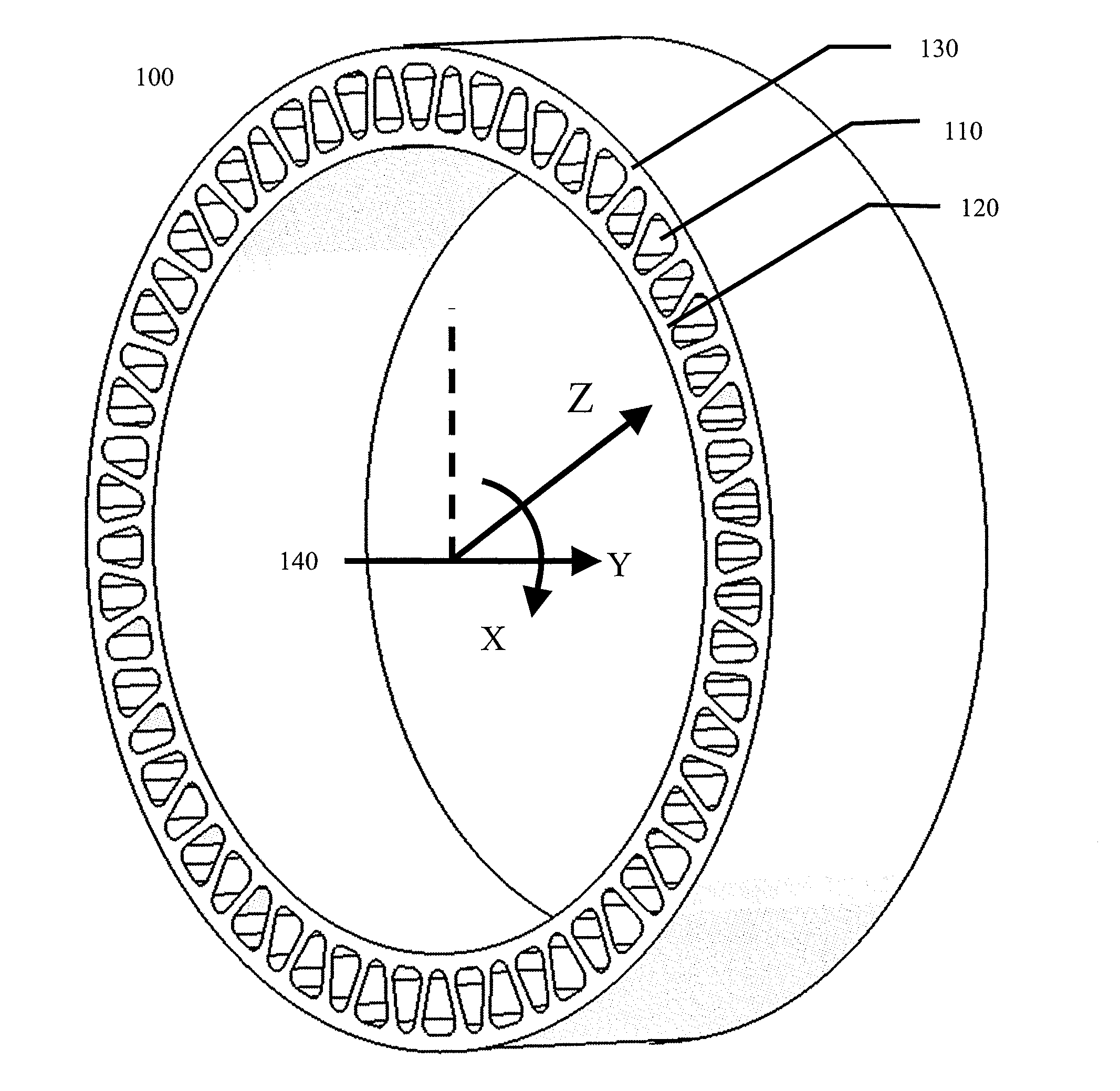
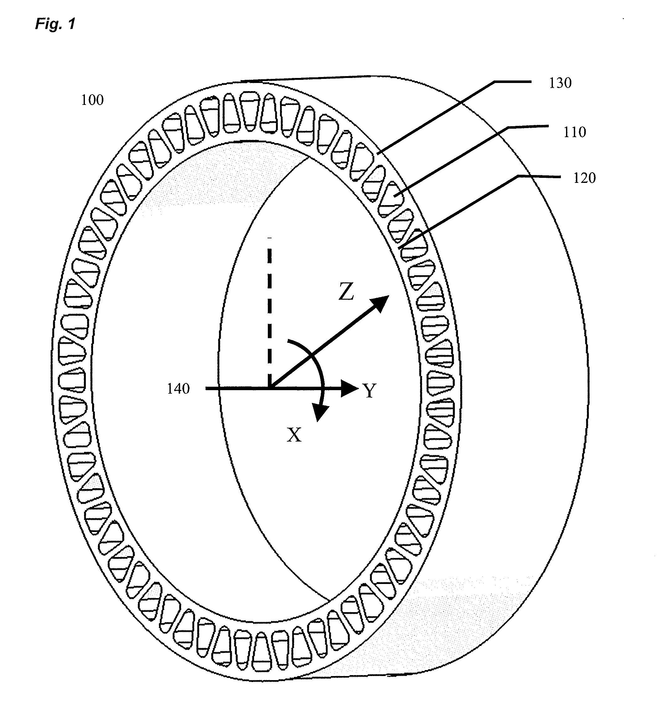
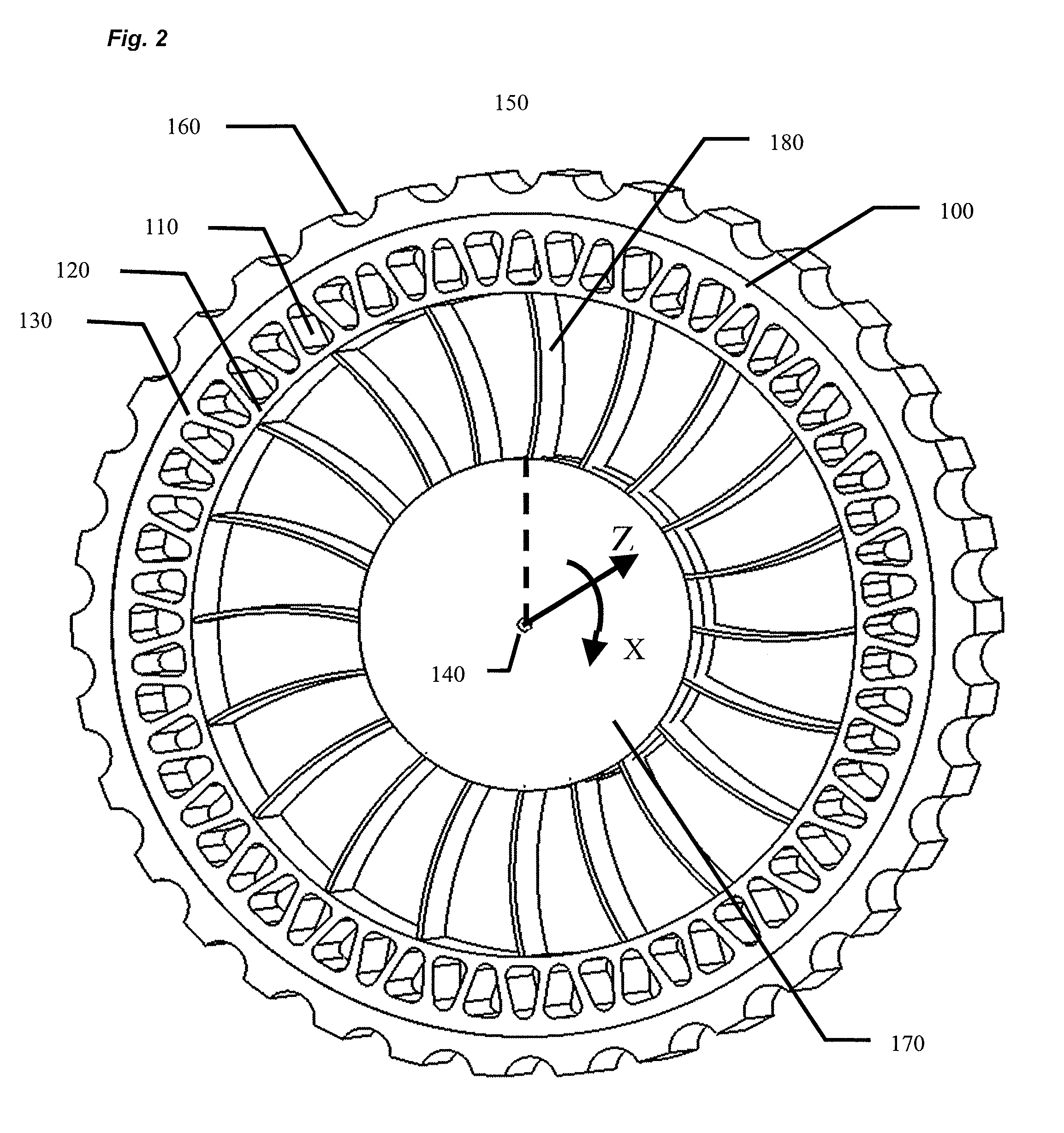
[0036]Reference will now be made in detail to embodiments of the invention, one or more examples of which are illustrated in the Figures. Each example is provided by way of explanation of the invention, and not meant as a limitation of the invention. For example, features illustrated or described as part of one embodiment can be used with another embodiment to yield still a third embodiment.

DEFINITIONS

[0037]The following terms are defined as follows for this disclosure, with material properties referring to those at ambient temperature, unless otherwise noted:

[0038]“Wheel” or “Hub” refers to any structure for supporting the tire and capable of attachment to a vehicle axis, and such terms are interchangeable herein.

[0039]“Modulus” means Young's tensile modulus of elasticity measured per ISO 527-1 / -2. “Young's Modulus,”“tensile modulus,” and “modulus” are used interchangeably herein.

[0040]“Secant Modulus” is the tensile stress divided by the tensile strain for any given point on the t...


PUM

PropertyMeasurementUnit
elongationaaaaaaaaaa
widthaaaaaaaaaa
outer diameteraaaaaaaaaa

Abstract

The present invention provides an annular beam of monolithic construction of one homogeneous material and a related efficient, low-cost non-pneumatic tire. Specific geometric design, combined with nonlinear elastomer physical properties, enable the suppression of all reinforcing belts, continuous fibers, or other strengthening layers in the annular beam. The annular beam consists of at least two bands that are continuous in the circumferential direction and connected by a web geometry. The non-pneumatic tire consists of the annular beam, a ground contacting portion, a central wheel, and a plurality of web spokes that connect the wheel and beam. When the tire is loaded to a design load against a flat surface over a design contact length, a contact area of essentially uniform pressure is produced, while the load is transmitted from the beam to the hub via tension in the web spokes. The tire can be economically manufactured.

Description

PRIORITY CLAIM[0001]This application claims the benefit of previously filed U.S. Provisional Patent Application entitled “Circumferential Beam of Homogeneous Material and Non-Pneumatic Tire”, given the Application No. 61 / 835,549, filed on 15 Jun. 2013, which is hereby incorporated by reference in its entirety. Furthermore, where a definition or use of a term in a reference, which is incorporated by reference herein, is inconsistent or contrary to the definition of that term provided herein, the definition of that term provided herein applies and the definition of that term in the reference does not apply.TECHNICAL FIELD OF THE INVENTION[0002]The present invention is in the field of non-pneumatic tires and related technologies. The application scope includes low-cost, efficient designs for tires. In manufacturing, the field includes high-pressure thermoplastic injection, reaction injection, and cast molding. The material science field involves thermoplastic and thermoset elastomers h...

Claims


Application Information

Patent Timeline
Patent Type & Authority Applications(United States)
IPC IPC(8): B60C7/00B29D30/02
CPCB60C7/00B29L2030/006B60C2007/005B29D30/02B60C7/18
Inventor THOMPSON, RONALD H.
Owner CAMOPLASY INC
Why Eureka
Try Eureka