Magnetic particle separator for thermal systems

a technology of magnetic particle separator and thermal system, which is applied in the direction of sedimentation settling tank, domestic heating details, space heating and ventilation details, etc. it can solve the problems of affecting the design parameters, affecting the operation efficiency of the system, so as to facilitate the fall down and accumulation of particles

Active Publication Date: 2014-12-18
CALEFFI
View PDF3 Cites 37 Cited by
  • Summary
  • Abstract
  • Description
  • Claims
  • Application Information

AI Technical Summary

Benefits of technology

[0014]In particular, the solution according to the present invention differs from known particle separators, in that the magnets for attracting the magnetic particles are positioned outside a quieting chamber, below a particle separation chamber, where the substantial reduction of the fluid velocity tends to create a quieting zone that facilitates the fall down and accumulation of particles, and in particular the magnetic attraction of the magnetic particles towards a peripheral wall of the same quieting chamber.
[0015]A transition zone may be advantageously provided between the particle separation chamber and the quieting chamber to damp any whirling motion in the fluid, allowing the separated particles to freely fall down.

Problems solved by technology

If these dirty particles and / or magnetic particles resulting from corrosion are not removed, they tend to accumulate in critical parts of the heating system, such as valves and / or fluid circulation pumps, thus altering the designing parameters or even causing damage to the system.
In a similar magnetic separator device, in addition to not being able to hold non-magnetic particles of the fluid, the withdrawal of the magnet and the removal of the magnetic particles would necessarily require the container to be opened, consequently stopping the circulation of the pressurised fluid by providing suitable valves upstream and downstream of the same separator device.
With this kind of magnetic separator, it is therefore not possible to perform cleaning operations and removal of the sludge while the system is working.

Method used


Image

  • Magnetic particle separator for thermal systems
  • Magnetic particle separator for thermal systems
  • Magnetic particle separator for thermal systems

Examples


Embodiment Construction

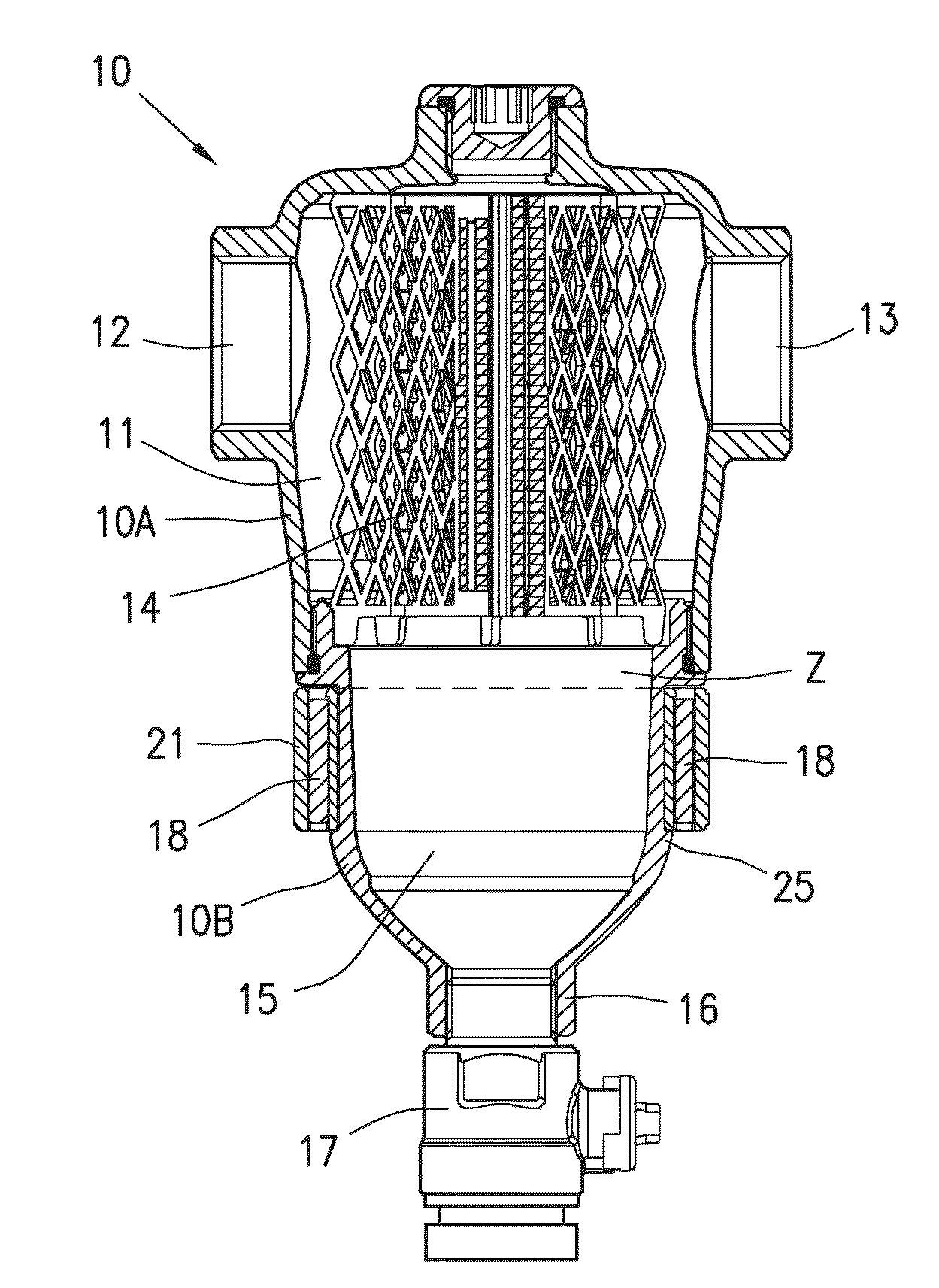
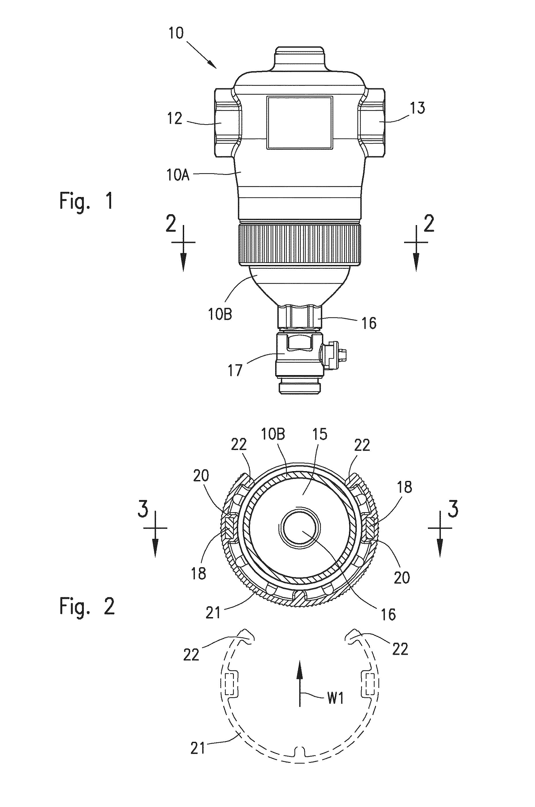
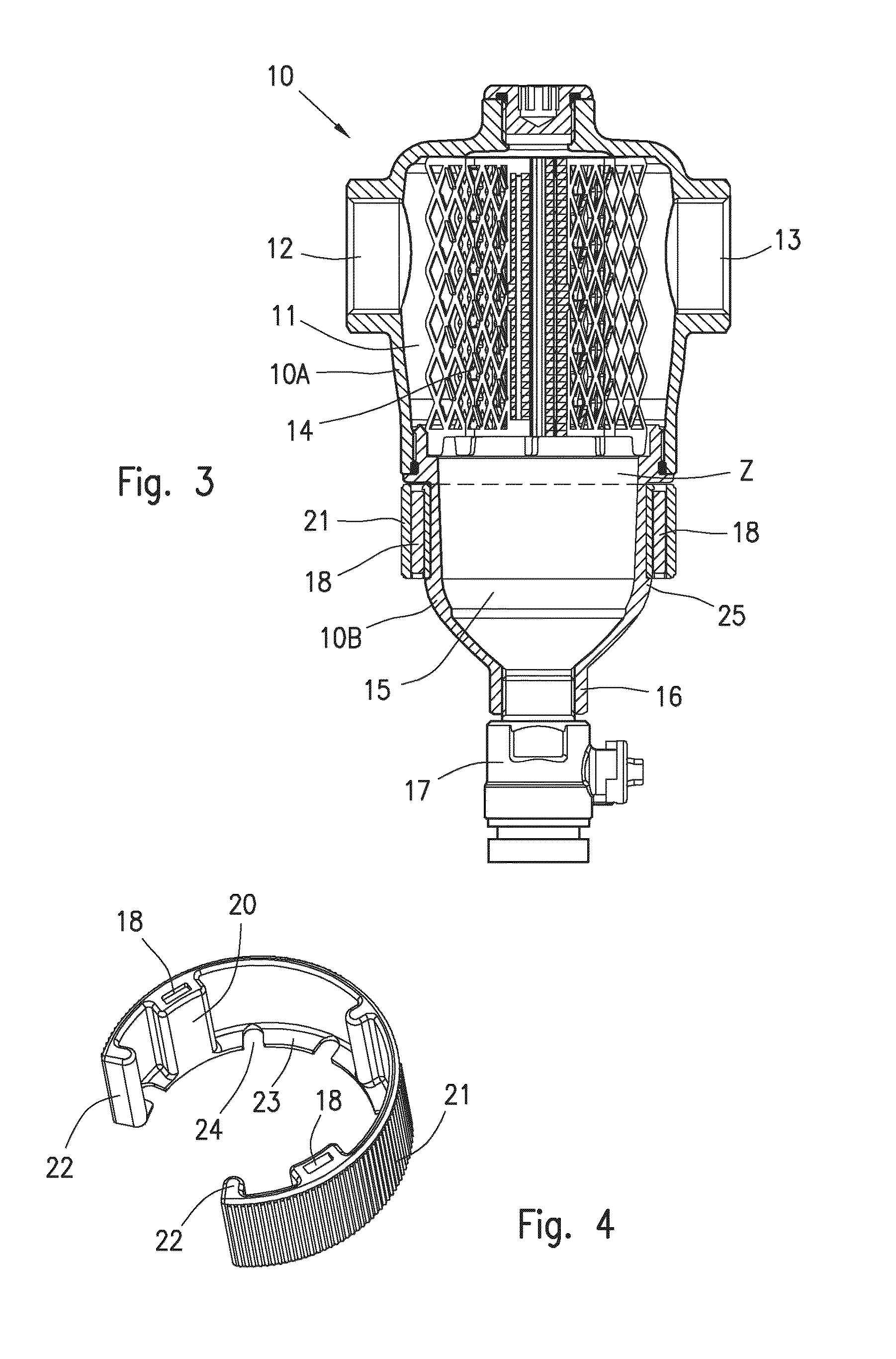
[0024]With reference to FIGS. 1-4 a first embodiment of a magnetic particle separator according to the invention will be now described.

[0025]The magnetic particle separator comprises a hollow body 10 made of brass or another suitable non-magnetic material, consisting of a cup shaped upper part 10A, and a cup shaped lower part 10B tightly screwed together. The upper part 10A of the body defines a first chamber 11, also referred to as particle separation chamber for the dirt entrained by the thermal fluid circulating in a heating system; the upper part 10A of the body is also provided with an inlet port 12 and an outlet port 13 for the fluid, and comprises means 14 for deviating and reducing the velocity of the fluid, that is suitable to allow a separation by gravity of the dirt particles entrained by the fluid.

[0026]The means 14 for the deviation and the reduction of the fluid velocity may be of any type; for example, it can take the form of a removable filtering cartridge consisting...


PUM

PropertyMeasurementUnit
magneticaaaaaaaaaa
non-magnetic aaaaaaaaaa
velocityaaaaaaaaaa

Abstract

A magnetic particle separator (10) suitable for separating magnetic and non-magnetic particles from a thermal fluid flowing in a heating system. The magnetic particle separator (10) comprises a hollow body (10A, 10B) configured with an upper particle separation chamber (11) and for circulation of the thermal fluid between an inlet and an outlet port (12, 13), and a quieting chamber (15) beneath the particle separation chamber (11) for accumulation of the particles separated from the fluid: an annular support element (21) for permanent magnets (18) being removably fastened outside the quieting chamber (15) of the separator (10).

Description

BACKGROUND OF THE INVENTION[0001]The invention relates to a device for separating particle material from a fluid circulating in a heating system, that accumulates and is periodically purged as sludge; in particular the invention is directed to a magnetic particle separator suitable for separating both magnetic or ferrous particles resulting from the internal corrosion of pipes and / or equipments of a heating system, as well as non-magnetic or non-ferrous particles resulting from dirt in the flowing thermal fluid. Although, according to the invention the magnetic particle separator is suitable for any application, it is particularly suitable for application both in household and centralized heating systems for civil and / or industrial use.STATE OF THE ART[0002]As is well known, the thermal fluid that circulates in a heating system tends to entrain a quantity of non magnetic particles due to the dirt present or formed in the same fluid, and magnetic particles due to the internal corrosi...

Claims


Application Information

Patent Timeline
Patent Type & Authority Applications(United States)
IPC IPC(8): B03C1/30
CPCB03C1/30B01D21/0009B01D21/0039B01D21/2483B03C1/288F24D19/0092B01D35/06B03C2201/18B03C2201/20B03C2201/28
Inventor CALEFFI, MARCO
Owner CALEFFI
Why Eureka
Try Eureka