Optical reflecting element and actuator

a technology of optical reflection and actuator, applied in optics, instruments, electrical devices, etc., can solve the problems of power consumption and suppress achieve the effect of suppressing the drive efficiency decrease, reducing power consumption, and small display system

Active Publication Date: 2014-12-18
PANASONIC INTELLECTUAL PROPERTY MANAGEMENT CO LTD
View PDF3 Cites 70 Cited by
  • Summary
  • Abstract
  • Description
  • Claims
  • Application Information

AI Technical Summary

Benefits of technology

[0012]In this configuration, the monitor part is deformed by the inertia force generated when the movable plate rotates. In other words, the optical reflecting device itself has a monitoring function, allowing the display system to be small. Furthermore, since the monitor part is deformed by the inertia force generated by the motion of the reflecting surface, the motion of the reflecting surface can be detected directly. The monitor part is provided in a reg...

Problems solved by technology

This suppresses a decrease in the dri...

Method used


Image

  • Optical reflecting element and actuator
  • Optical reflecting element and actuator
  • Optical reflecting element and actuator

Examples


first exemplary embodiment

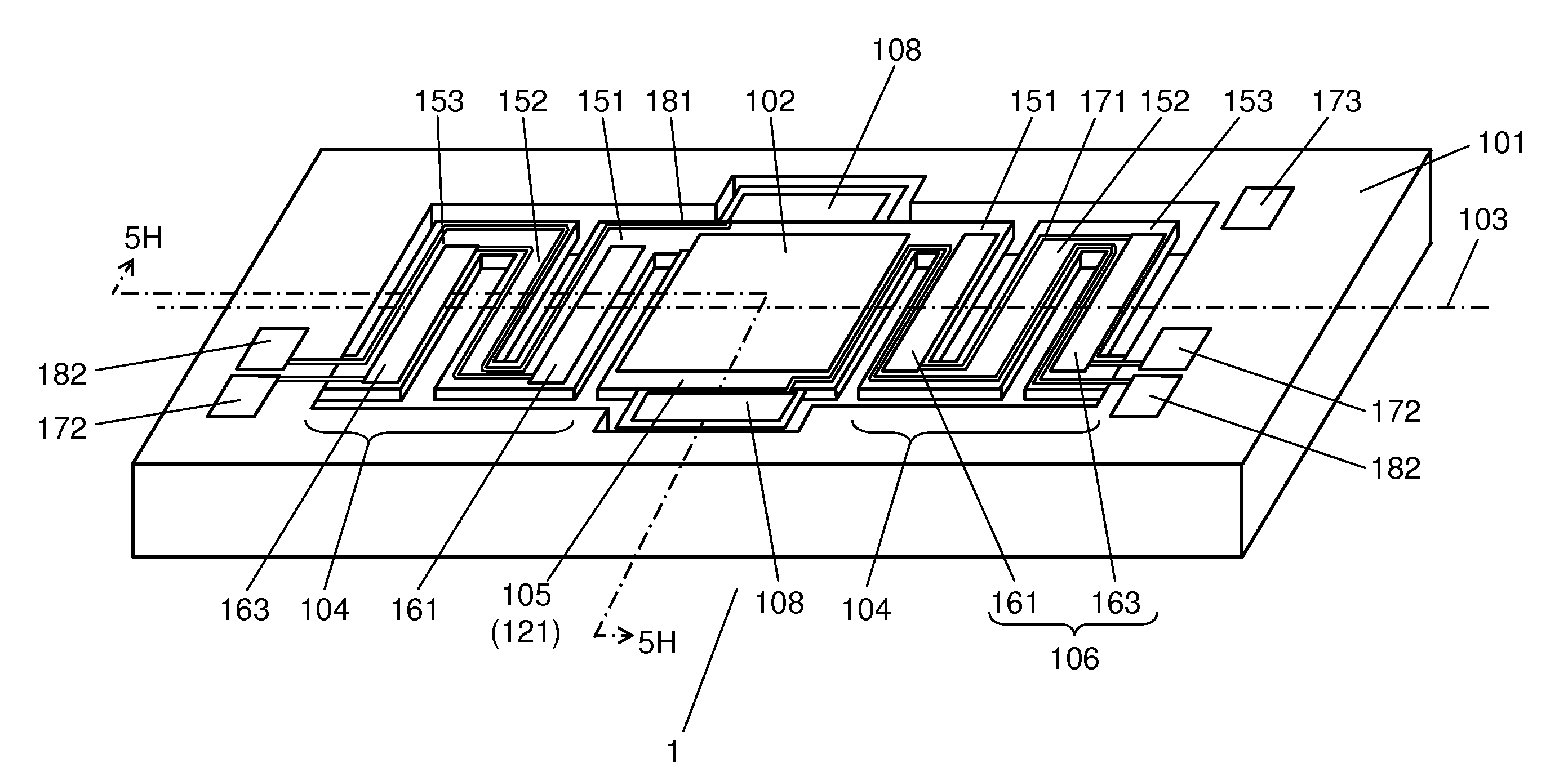
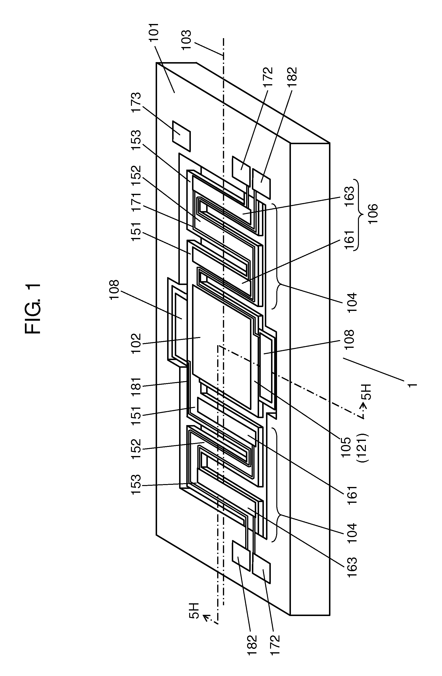
[0036]An optical reflecting device according to a first exemplary embodiment of the present invention will now be described with reference to drawings. FIG. 1 is a perspective view of optical reflecting device 1 according to the present exemplary embodiment.

[0037]Optical reflecting device 1 includes movable plate 105, support portions 104 as first support portions, drive parts 106 as first drive parts, fixed frame 101, and monitor part 108 for detecting the rotation of movable plate 105. Movable plate 105, which is disposed in fixed frame 101, includes reflecting surface 121 on which mirror part 102 is formed. Support portions 104 are also disposed in fixed frame 101, and are connected to movable plate 105. First drive parts 106 are provided on support portions 104 so as to rotate movable plate 105 about rotation axis 103 as a first axis. Fixed frame 101 as a first frame, is connected to support portions 104. In other words, fixed frame 101 and movable plate 105 are coupled to each ...

second exemplary embodiment

[0066]An optical reflecting device according to a second exemplary embodiment of the present invention will now be described with reference to FIG. 6. FIG. 6 is a top view of optical reflecting device 501 according to the present exemplary embodiment.

[0067]Optical reflecting device 501 includes fixed frame 502 as a first frame, movable frame 503 as a second frame disposed in fixed frame 502, and mirror part 504 disposed in movable frame 503. Mirror part 504 and movable frame 503 are held by a pair of second support portions 506 so that mirror part 504 can rotate about second rotation axis 510. Fixed frame 502 and movable frame 503, on the other hand, are held by a pair of first support portions 505 so that movable frame 503 can rotate about first rotation axis 509.

[0068]Each of first support portions 505 has a meandering structure in which four vibrating beams 5051-5054 are connected together in an accordion fold. Vibrating beams 5051-5054 are made of silicon and first drivers 5071-...


PUM


Abstract

An optical reflecting device includes a movable plate having a reflecting surface, a first support portion, a first drive part, a first frame, and a monitor part for detecting the rotation of the movable plate. The first support portion is connected to the movable plate. The first drive part is formed in the first support portion and rotates the movable plate about a first axis. The first frame contains the movable plate and the first support portion, and is connected to the first support portion. The monitor part extends from that portion of the outer periphery of the movable plate which is most distant from the first axis.

Description

TECHNICAL FIELD[0001]The present invention relates to an optical reflecting device for use in a laser printer, a bar-code reader, or an image projection device such as a head-up display or a head-mounted display. The present invention also relates to an actuator having a similar structure to the optical reflecting device.BACKGROUND ART[0002]Optical scanners, which scan a light flux emitted from a light source such as a laser or a light-emitting diode, are used in practical applications. These optical scanners are classified into a one-dimensional scanning type such as a laser printer or a bar-code reader, and a two-dimensional scanning type such as an in-car radar or a projection display device. For these optical scanners, it is important to detect the position of the mirror surface, and hence, various efforts have been made to provide a monitoring function for achieving this detection.[0003]For example, Patent Literature 1 discloses a method of detecting the position of the mirror ...

Claims


Application Information

Patent Timeline
IPC IPC(8): G02B26/10G02B26/08
CPCG02B26/0858G02B26/105G02B26/101H04N1/113
Inventor NAKAZONO, SHINSUKEKUROZUKA, AKIRAYAMAMOTO, YUTAKOMAKI, KAZUKI
Owner PANASONIC INTELLECTUAL PROPERTY MANAGEMENT CO LTD
Why Eureka
Try Eureka