Electrochemical device
- Summary
- Abstract
- Description
- Claims
- Application Information
AI Technical Summary
Benefits of technology
Problems solved by technology
Method used
Image

Examples
first embodiment
[0068]The electrochemical device pertaining to the first embodiment of the present invention is explained.
[0069][Overall Configuration of Electrochemical Device]
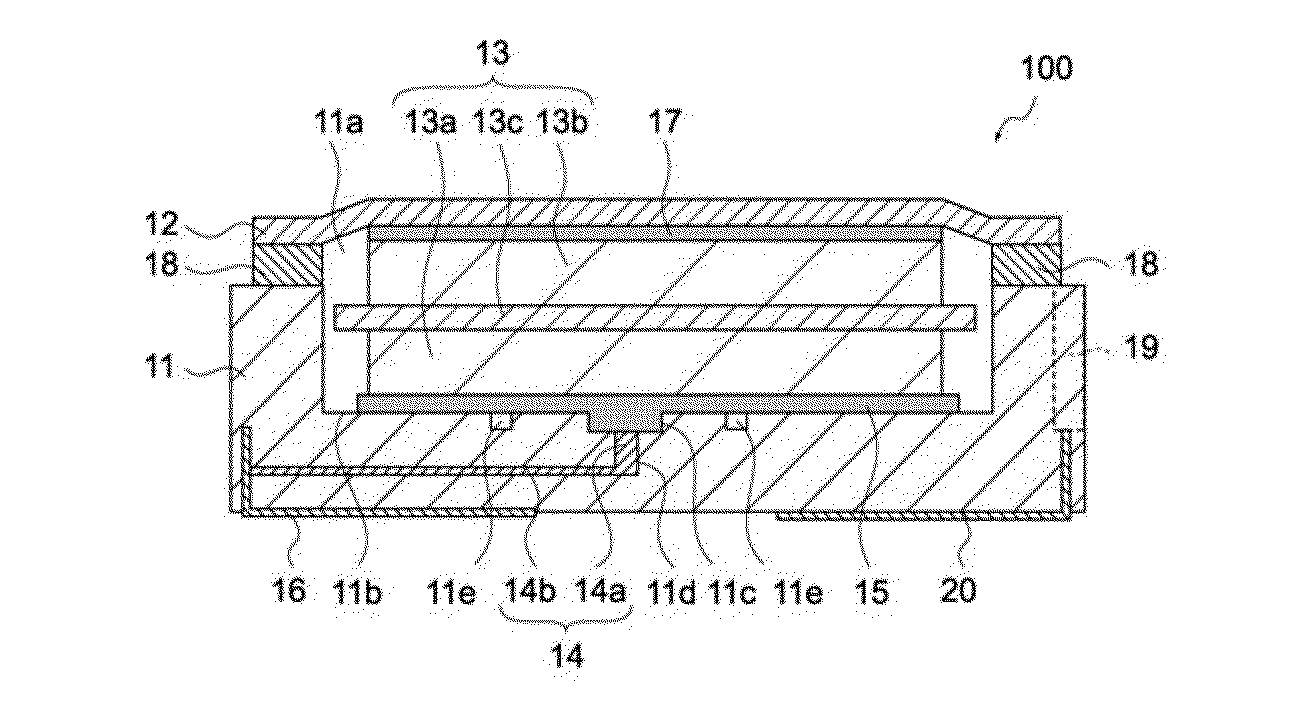
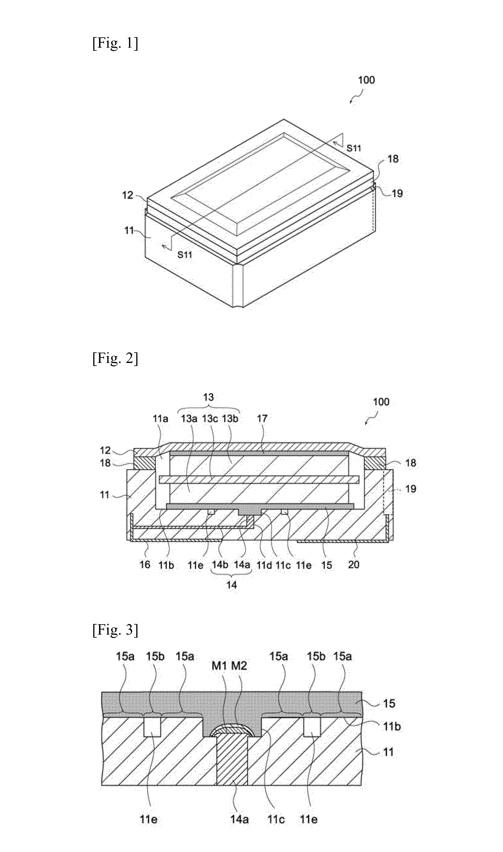
[0070]FIG. 1 is a perspective view showing the appearance of an electrochemical device 100 pertaining to this embodiment. FIG. 2 is a section view of the electrochemical device 100, cut along line S11-S11 (FIG. 1). FIG. 3 is an enlarged view of a part of the section view in FIG. 2. As shown in these figures, the electrochemical device 100 has a case 11, lid 12, electric storage element 13, positive electrode wiring 14, positive electrode bonding layer 15, positive electrode terminal 16, negative electrode bonding layer 17, seal ring 18, negative electrode wiring 19, and negative electrode terminal 20.
[0071]As shown in FIG. 2, the electrochemical device 100 is constituted in such a way that the case 11 and lid 12 are joined via the seal ring 18 and the electric storage element 13 and electrolyte are sealed in a solution chamb...
second embodiment
[0097]The electrochemical device pertaining to the second embodiment of the present invention is explained. It should be noted that, since the only difference between this embodiment and first embodiment is the configuration of the groove, other parts are denoted by the same symbols used on the electrochemical device pertaining to the first embodiment, and are not explained.
[0098]FIG. 8 is an enlarged view of a part of the section drawing of the electrochemical device pertaining to this embodiment. As shown in this figure, a gas release part 21 is formed in the groove 11e of the electrochemical device. The gas release part 21 is electrically connected to the positive electrode bonding layer 15 and made of a material that releases gas as a result of electrolytic corrosion upon contacting the electrolyte when the electrochemical device is charging.
[0099]To be specific, the gas release part 21 may have the same layer structure as that of the via hole part 14a. FIG. 9 is a schematic dra...
example 1
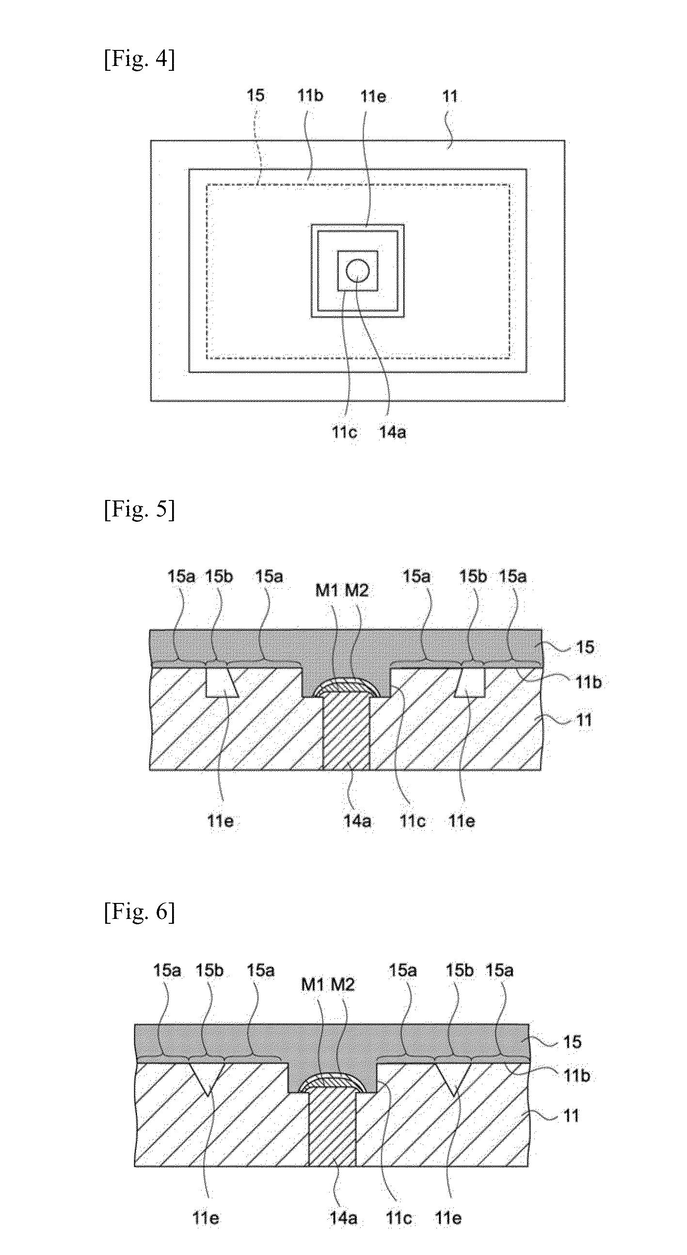
[0105]A via hole is formed in the bottom face of the case and a groove is formed around the via hole. The groove has an inverted-triangle cross-section (refer to FIG. 6) of 100 μm in width and 100 μm in depth. When conductive bonding material was applied on the bottom face of the case, gas was sealed in the deepest part of the groove.
PUM
 Abstract
Description
Claims
Application Information
 - Generate Ideas
- Intellectual Property
- Life Sciences
- Materials
- Tech Scout
- Unparalleled Data Quality
- Higher Quality Content
- 60% Fewer Hallucinations
Browse by: Latest US Patents, China's latest patents, Technical Efficacy Thesaurus, Application Domain, Technology Topic, Popular Technical Reports.
© 2025 PatSnap. All rights reserved.Legal|Privacy policy|Modern Slavery Act Transparency Statement|Sitemap|About US| Contact US: help@patsnap.com