
Ultrasound diagnostic device, ultrasound diagnostic method, and computer-readable medium having recorded program therein

a diagnostic device and ultrasound technology, applied in the direction of instruments, ultrasonic/sonic/infrasonic image/data processing, image enhancement, etc., can solve the problems of not taking diagnostic results as objective truths, diagnostic parts are not precisely represented, and medical workers are under a great burden

Inactive Publication Date: 2014-12-18
KONICA MINOLTA INC
View PDF6 Cites 7 Cited by
  • Summary
  • Abstract
  • Description
  • Claims
  • Application Information

AI Technical Summary

Benefits of technology

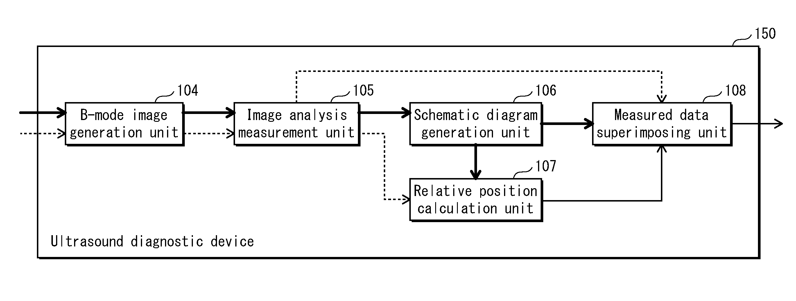
The present invention aims to improve ultrasound diagnostics by providing an ultrasound diagnostic device that can create examination reports with proper reliability. The device analyzes multiple ultrasound images and generates a schematic diagram of the diagnostic target based on the shape of the target analyzed from material images. It also calculates the relative position of the specific part shown in the diagnostic image with respect to the shape of the diagnostic target and identifies the position on the schematic diagram that corresponds to the position of the specific part. The device then superimposes data of the diagnostic value on the identified position on the schematic diagram. This invention simplifies the examination reports and makes them more accurate in representing the position of the plaque in the blood vessel.

Problems solved by technology

Since one tomographic image covers only several centimeters range of the blood vessel, a patient having no expert knowledge cannot determine a position of a plaque part of the blood vessel only by seeing such an ultrasound image, and cannot take diagnostic results as an objective truth.
However, there is a problem that a diagnostic part is not precisely represented because the plaque drawn in an examination report even by medical workers is often in handwriting with rough brush strokes.
On the other hand, it is a great burden for medical workers, who are under pressure of daily tasks, to precisely draw the diagnostic part for the schema included in the examination report.

Method used


Image

  • Ultrasound diagnostic device, ultrasound diagnostic method, and computer-readable medium having recorded program therein
  • Ultrasound diagnostic device, ultrasound diagnostic method, and computer-readable medium having recorded program therein
  • Ultrasound diagnostic device, ultrasound diagnostic method, and computer-readable medium having recorded program therein

Examples


embodiment 1

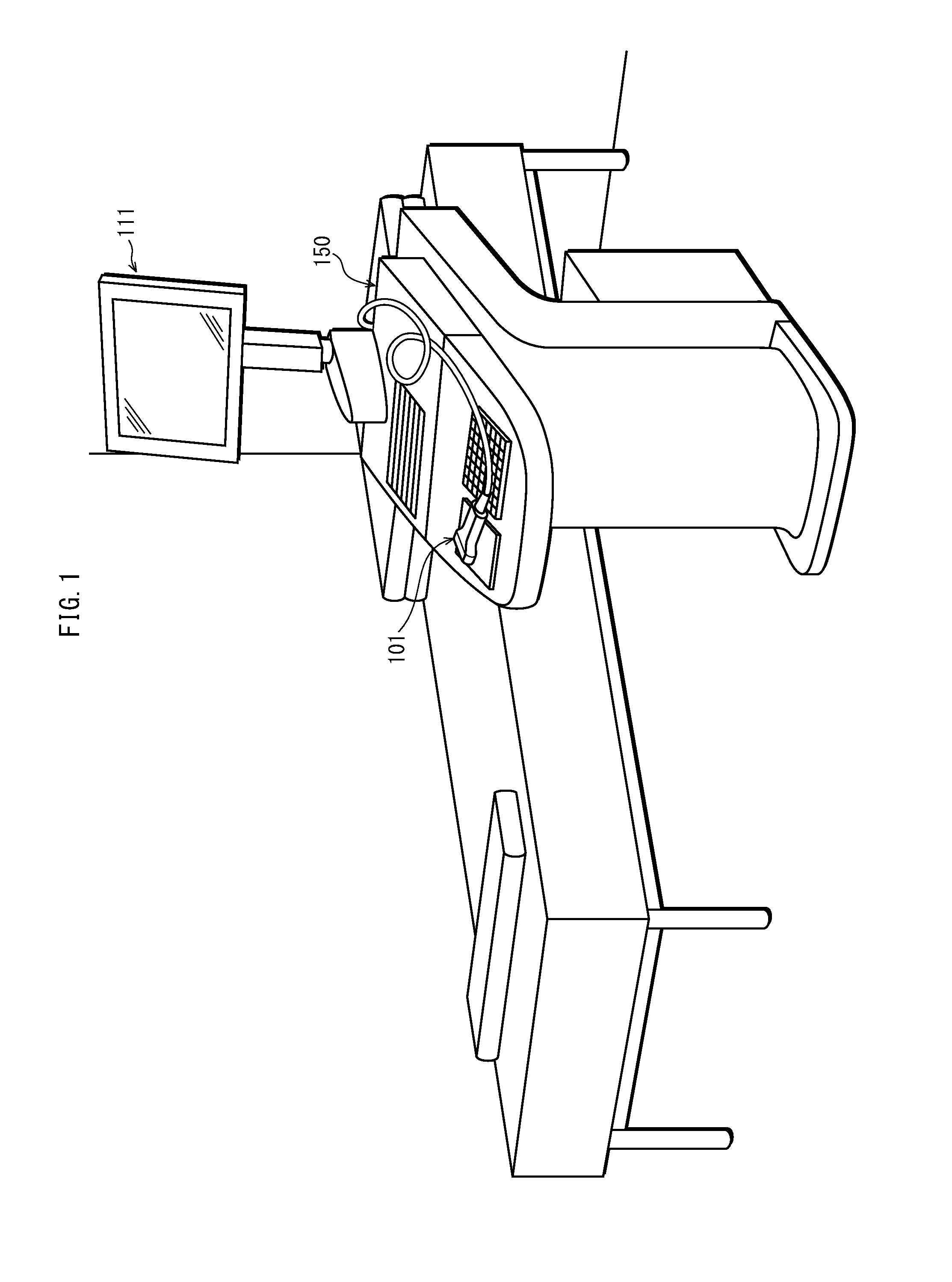
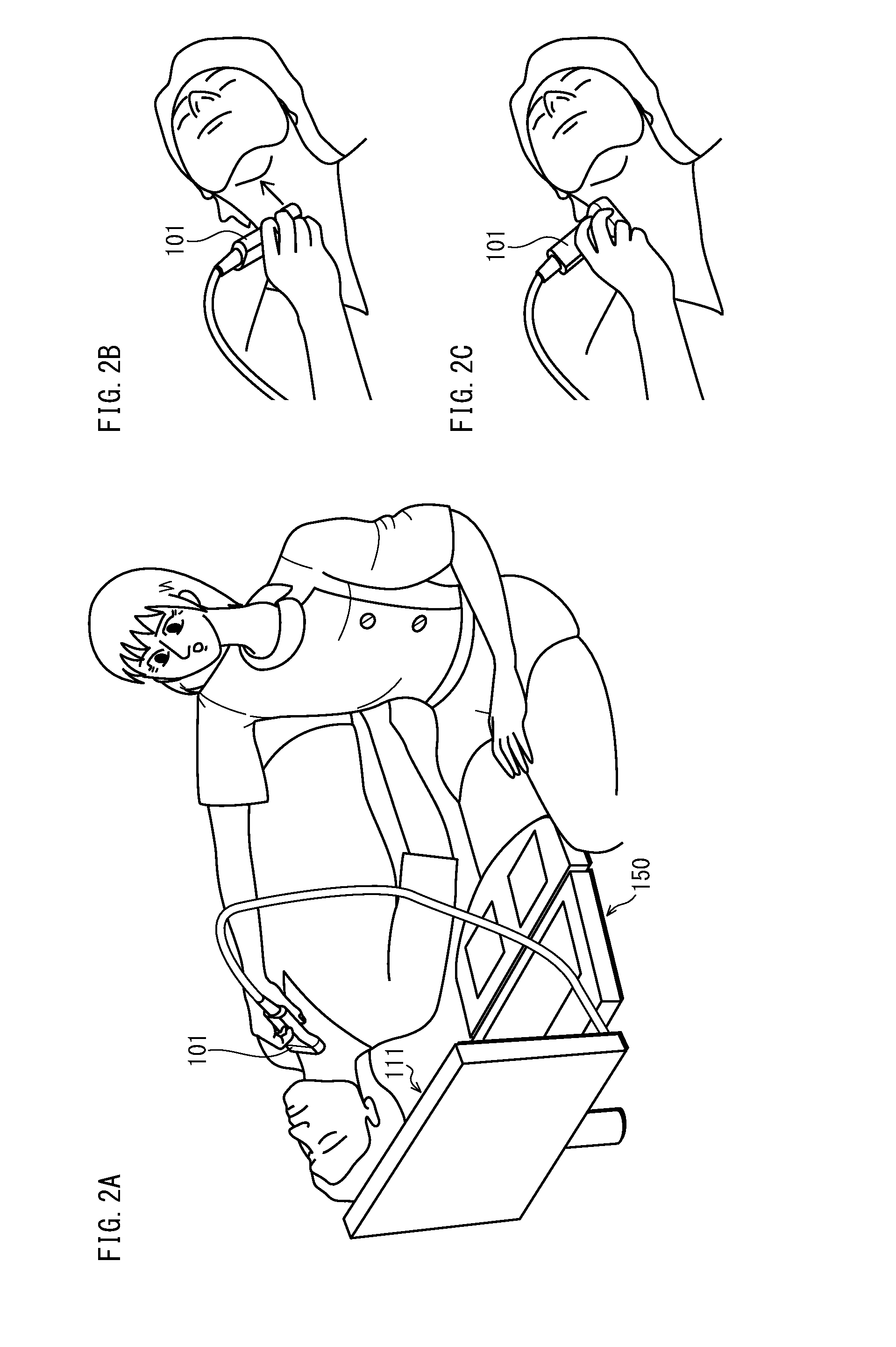
[0039]The following describes a schematic structure of an ultrasound diagnostic device relating to the present embodiment. FIG. 1 shows an outer appearance structure of an ultrasound diagnostic device 150 relating to the present embodiment. As shown in the figure, the ultrasound diagnostic device 150 is medical equipment used in medical practice, and is composed of a probe 101 and a display unit 111 that are integrated into one device.

[0040]The probe 101 transmits ultrasound, and receives an ultrasound signal reflected from a subject.

[0041]The display unit 111 is an LCD (Liquid Crystal Display) or the like, and displays B-mode images, a schematic diagram, diagnostic values, and so on that are generated from the reflected ultrasound signal.

[0042]The ultrasound diagnostic device 150 is a processing device that provides a diagnostic imaging function and a network communication function in order to realize ultrasound diagnosis. The diagnostic imaging function is a function of forming an...

embodiment 2

[0119]In Embodiment 1, the relative position information is calculated from the transverse images, and the data of the diagnostic value analyzed from the longitudinal image is superimposed on the schematic diagram based on the relative position information. However, there is a possibility that the relative position information is wrong, and the display unit 111 displays the diagnostic value on a position which is shifted from the operator's intended position.

[0120]FIG. 17 is a block diagram showing an internal structure of an ultrasound diagnostic device 152 relating to Embodiment 2. The ultrasound diagnostic device 152 shown in FIG. 17 is different from the ultrasound diagnostic device 150 shown in FIG. 4, in terms of additionally including constituent elements which are not shown in FIG. 4, namely, a user designation input unit 121 and a correction unit 122.

[0121]The user designation input unit 121 receives a correction request on a schematic diagram from the operator by receiving...

embodiment 3

[0126]In Embodiment 1, in the case where a CG schematic diagram is generated, relative position information is generated based on a 3D geometric model. In the present embodiment compared with this, also in the case where a schema schematic diagram is generated, relative position information is generated based on a 3D geometric model. FIG. 19 is a flow chart showing a processing procedure of relative position calculation based on a 3D geometric model in the longitudinal direction in Embodiment 3. Since the flow chart in FIG. 19 is based on the flow charts in FIG. 14 and FIG. 15, steps in FIG. 19 that are the same as the steps in FIG. 14 and FIG. 15 have the same reference signs.

[0127]In the flow chart FIG. 19, a longitudinal image graph is generated in which the horizontal axis represents coordinates in the longitudinal direction in the longitudinal image, and the vertical axis represents the change Δde in IMT. In Step S12, a Y-shaped bifurcation is detected from a 3D geometry genera...


PUM


Abstract

An ultrasound diagnostic device processes ultrasound images obtained by ultrasound scanning on a diagnostic target. The ultrasound images include a set of material images for analyzing shape of the diagnostic target and a diagnostic image for analyzing a diagnostic value of a specific part of the diagnostic target. An image analysis measurement unit generates a schematic diagram showing schematic shape of the diagnostic target based on the shape of the diagnostic target. A relative position calculation unit calculates a relative position of local shape of the specific part to the shape of the diagnostic target. A diagnostic value superimposing unit identifies a position on the schematic shape of the diagnostic target that corresponds to a position of the specific part based on the relative position, and superimposes data of the diagnostic value on the identified position on the schematic shape of the diagnostic target shown in the schematic diagram.

Description

[0001]This application is based on an application No. 2013-127258 filed in Japan on Jun. 18, 2013, the contents of which are hereby incorporated by reference.BACKGROUND OF THE INVENTION[0002](1) Field of the Invention[0003]The present invention relates to an ultrasound diagnostic device and a diagnostic position identification method.[0004](2) Description of the Related Art[0005]According to the ultrasound diagnostic device and the diagnostic position identification method, ultrasound is transmitted to a subject by an ultrasound probe, and ultrasound reflected from the subject is received thereby to obtain ultrasound images in accordance with a reflected ultrasound signal. Medical workers observe such ultrasound images to diagnose whether arteriosclerosis and vascular disease exist.[0006]Known diagnostic targets of ultrasound diagnostic devices include intima-media thickness (hereinafter, referred to as IMT) and plaque. IMT indicates thickness of intima and media of vascular walls. ...

Claims


Application Information

Patent Timeline
Patent Type & Authority Applications(United States)
IPC IPC(8): G06T7/00A61B8/06A61B8/08
CPCG06T7/0012A61B8/5292G06T2207/30104G06T2207/10132G06T2207/30101A61B8/06A61B8/0891A61B8/466A61B8/483A61B8/5223G06T7/0014G16H50/30
Inventor TOJI, BUMPEIOHMIYA, JUNTOMA, TADAMASA
Owner KONICA MINOLTA INC
Learn More