Shielded connector

a shielding and connector technology, applied in the direction of electrical equipment, connection, coupling device connection, etc., can solve the problems of reducing the shielding effect and causing corrosion

Active Publication Date: 2014-12-18
YAZAKI CORP
View PDF80 Cites 16 Cited by
  • Summary
  • Abstract
  • Description
  • Claims
  • Application Information

AI Technical Summary

Benefits of technology

[0006]In a shielded connector in which, as described above, a braided conductor and shield shell are swaged by a shield ring to be electrically conductive with each other, a shielding circuit is formed by connecting the shielded connector to a case, with the result that a shielding effect is attained.

Problems solved by technology

Therefore, the portion where the braided conductor is in contact with the shield ring has a bimetallic contact, and there is a possibility that galvanic corrosion may occur to reduce the shielding effect.

Method used


Image

  • Shielded connector
  • Shielded connector
  • Shielded connector

Examples


Embodiment Construction

[0031]Hereinafter, an embodiment of the invention will be described with reference to the drawings.

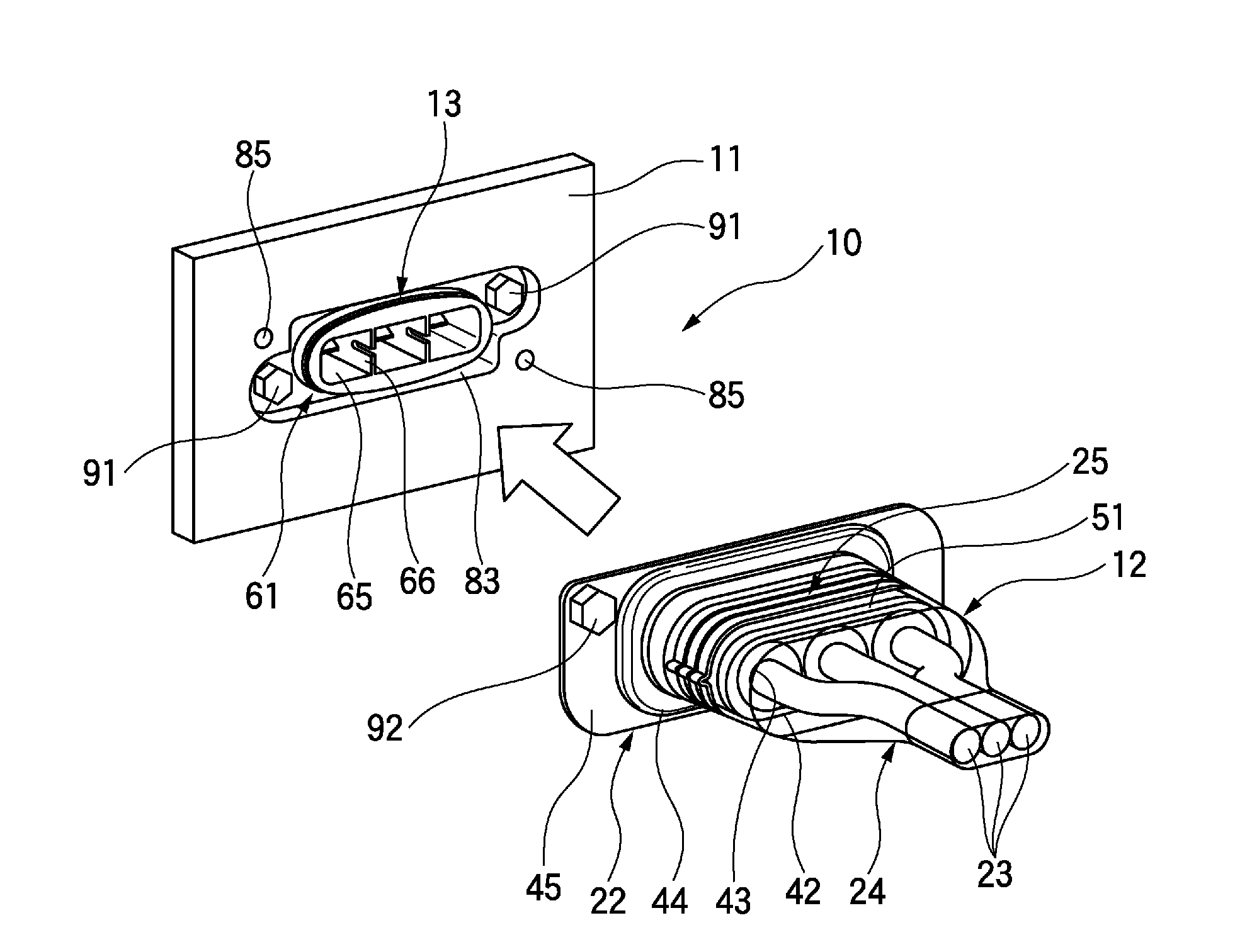
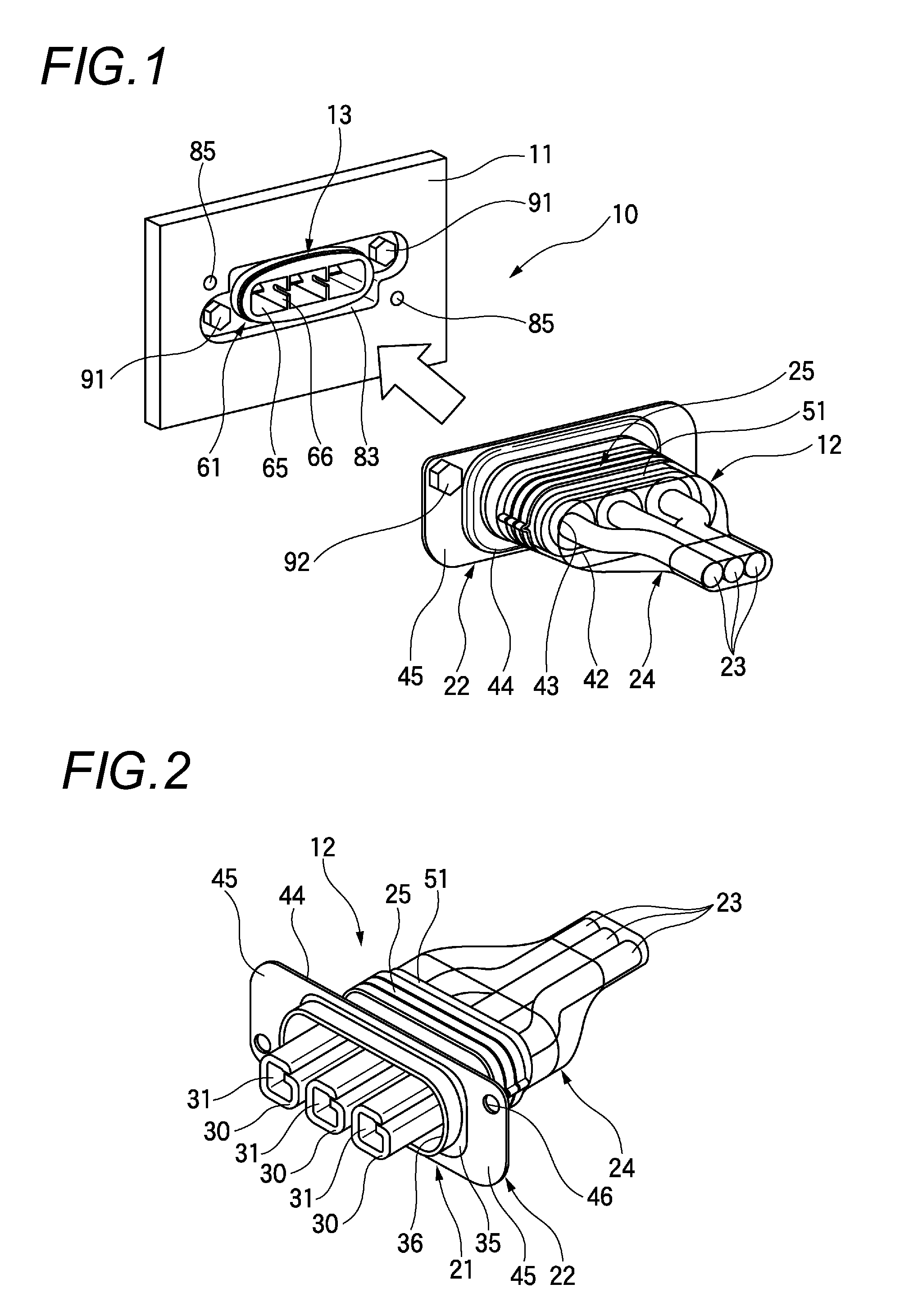
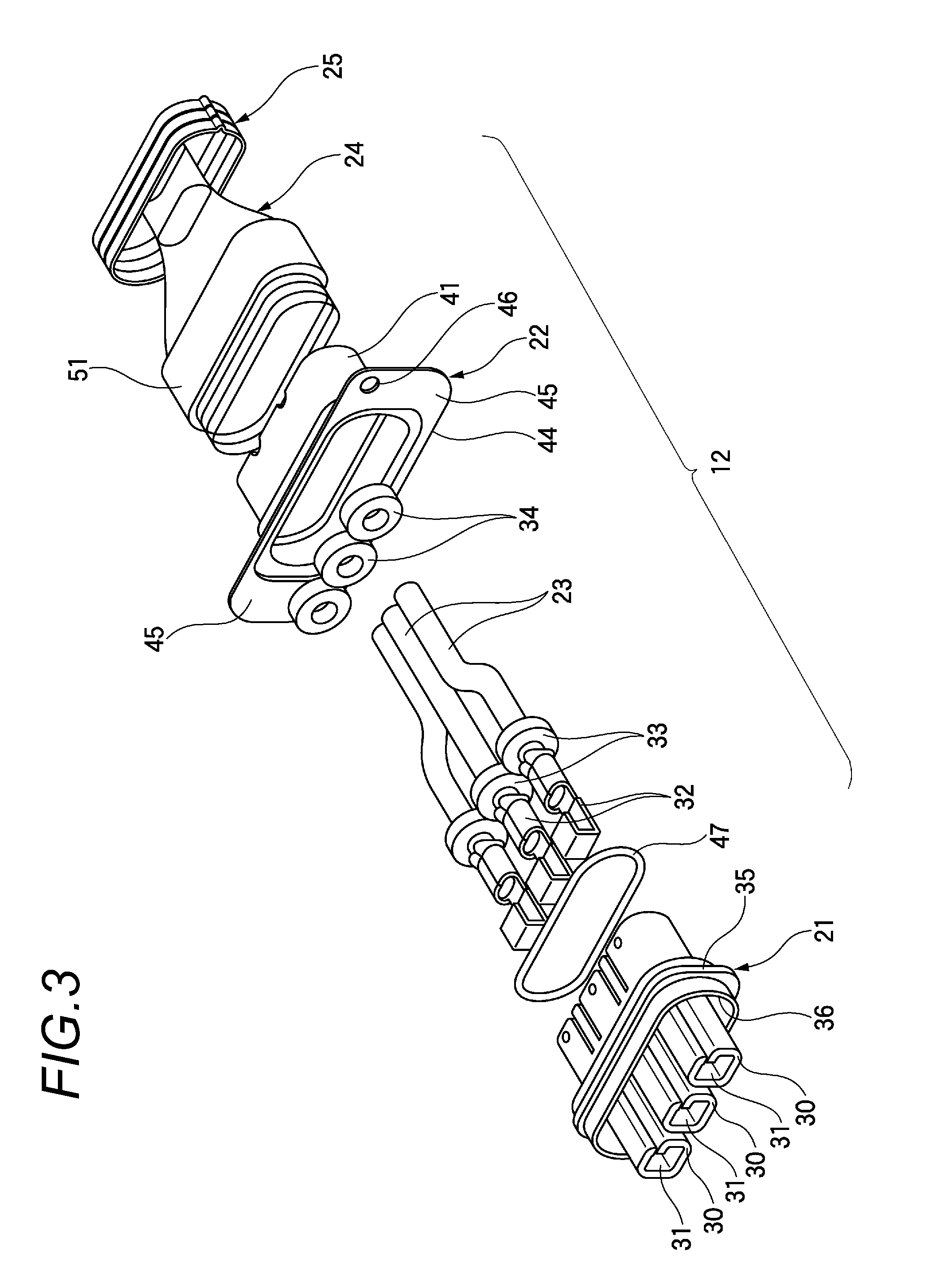
[0032]FIG. 1 is a perspective view of a portion where a male shielded connector and a female shielded connector are connected to each other, FIG. 2 is a perspective view of a male shielded connector of the embodiment, FIG. 3 is an exploded perspective view of the male shielded connector of the embodiment, FIG. 4 is a perspective view of the female shielded connector, FIG. 5 is an exploded perspective view of the female shielded connector, FIG. 6 is a perspective view of a connector attaching portion of a case to which the female shielded connector and the female shielded connector are to be attached, and FIG. 7 is a perspective view of the male shielded connector which is connected to the female shielded connector.

[0033]As shown in FIG. 1, a shield connecting portion 10 is configured by connecting a male shielded connector 12 to a female shielded connector 13 which is fixed to a case 1...


PUM


Abstract

The male shielded connector of the invention includes terminals which are connected to end portions of electric wires, a housing which contains the terminals, a shield shell which covers the housing, a braided conductor which is externally provided to the wire and is covered on the shield shell, and a shield ring which is swaged to the outer circumference of the braided conductor to fix the braided conductor in a state that the braided conductor is electrically connected to the shield shell, the shield ring being made of a metal material. An insulation layer is provided between the braided conductor and the shield ring.

Description

CROSS REFERENCE TO RELATED APPLICATIONS[0001]This is a Continuation application of U.S. application Ser. No. 14 / 110,754, filed Oct. 9, 2013 which is a National Stage Application of PCT application No. PCT / JP2012 / 060183, which was filed on Apr. 13, 2012 based on Japanese Patent Application (No. 2011-090410) filed on Apr. 14, 2011, the contents of which are incorporated herein by reference.BACKGROUND[0002]1. Field of the Invention[0003]The present invention relates to a shielded connector in which a braided conductor is fastened and electrically connected to a shield shell by a shield ring.[0004]2. Description of the Related Art[0005]A shielded connector is used as a connector for a wire harness in a hybrid electric vehicle (HEV), an electric vehicle (EV), or the like. A shielded connector includes: terminal-equipped electric wires in each of which a terminal is connected to an end portion of the wire; a housing which contains the terminals of the terminal-equipped wires; a shield she...

Claims


Application Information

Patent Timeline
Patent Type & Authority Applications(United States)
IPC IPC(8): H01R13/6593H01R13/6581
CPCH01R13/6581H01R13/6593H01R13/5205H01R13/5216H01R13/748
Inventor KOBAYASHI, MASAKI
Owner YAZAKI CORP
Why Eureka
Try Eureka