Apiculture

Active Publication Date: 2014-12-18
FLOWBEE AUSTRALIA PTY LTD
View PDF4 Cites 21 Cited by
  • Summary
  • Abstract
  • Description
  • Claims
  • Application Information

AI Technical Summary

Benefits of technology

[0098]Another advantage of the present invention is that the hive design can change substantially from the traditional box with removable frames. The whole hive may be made of the same molded material as the honeycomb sections and be built in such a way to minimize spaces for pests such as moths and beetles to breed. Traps for pests can also be built into the molded hive design. It is envisaged, but not limited to, that each of the honeycomb assemblies will be able to be removed from the hive ‘box’ for maintenance or replacement.
[0099]To facilitate draining of the honey, the viscosity of the honey can be reduced by circulating or blowing warm or hot air into the honeycomb assembly. The air can be blown into the spacing between adjacent honeycombs of the assembly once the first part has been retracted by initially lowering the pressure (or by some other means to retract the first part). More preferably the warm air may be circulated prior to retraction or both prior and subsequent to retraction. The warm or hot air can then circulate through the cells to warm the honey to improve drainage. This arrangement warms only the honeycomb assembly where the honey is stored and warm or hot air can be kept away from the bees in the brood box or in other parts of the hive. This may be an advantage of this construction of the invention.
[0100]The assembly can further comprise a lower collection area for honey which may be in the form of a honey trough a non-limiting example of which is illustrated as ref

Problems solved by technology

Collection of honey can be very laborious and time consuming.
It is estimated that the above time-consuming steps constitute approximately 90% of the beekeepers time required to collect honey from the hive.
Another disadvantage with conventional collecting techniques is the expense required in the provision of a honey shed, an extracting machine, and sometimes an automatic decapping machine.
Another disadvantage is that the hive can be quite damaged during the honey collecting process (also called the robbing process).
Another disadvantage is that the existing process greatly disturbs the bees and many bees may die during honey collection.
Also, there is always the annoyance (and sometimes potential danger) in bee stings during the robbing process of the hive.
Another

Method used


Image

  • Apiculture
  • Apiculture
  • Apiculture

Examples


Example

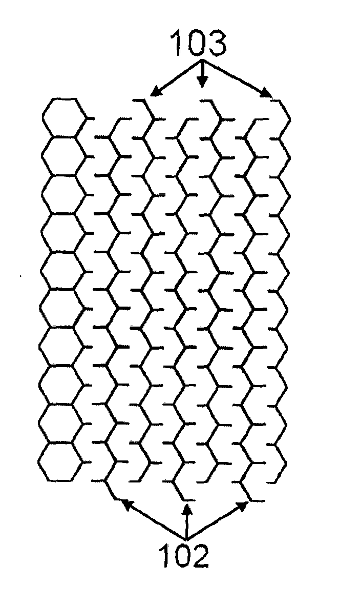
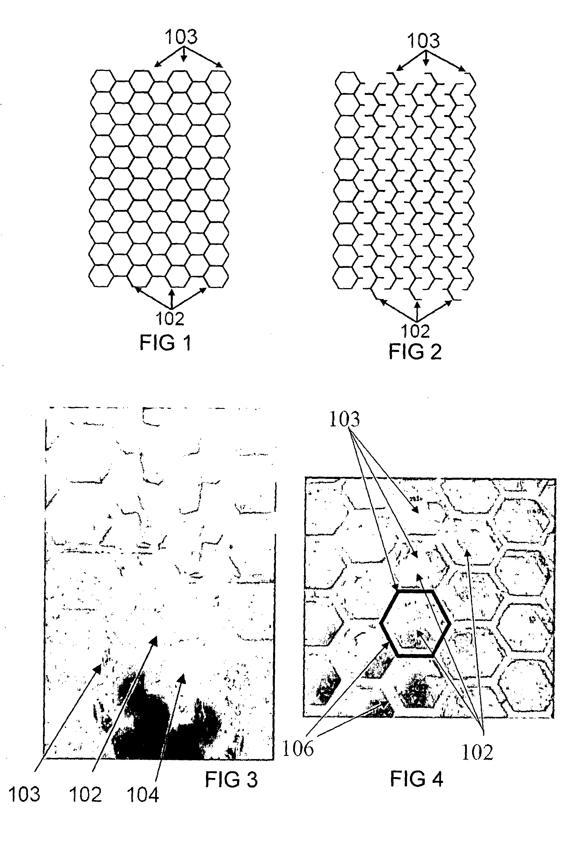
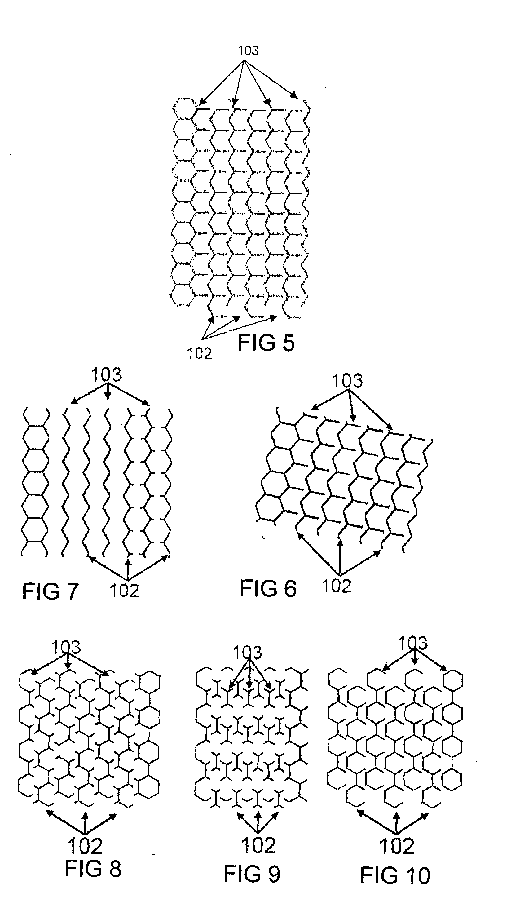
[0160]Throughout the following description the cell side wall will typically be hexagonal, which is the typical shape of a honeycomb cell. There may be circumstances where it may be desirable for the cell to have a different shape for instance an octagonal shape, oval shape, round shape, and the like. However the invention may be carried out with the cell having a hexagonal shape and this will be referred to throughout the specification for purposes of explanation.

[0161]Referring to FIGS. 1-12 there is illustrated various versions of a first aspect of the invention where the honeycomb is formed of at least two parts, each part comprising part of a cell wall, the parts being slideable relative to each other between a cell broken position and a cell formed position. This aspect of the invention may be termed the “vertical separation method”.

[0162]As the honeycombs are typically positioned in a vertical manner in the hive, the sliding movement can be a vertical (or up and down movement...


PUM


Abstract

An artificial honeycomb for use in a beehive and which enables honey to be removed from the honeycomb without removing the honeycomb from the hive, the honeycomb comprising cells and being formed of at least two parts which are moveable relative to each other between a cell formed position where the cells comprise side walls and an end wall to enable bees to fill the cell with honey, and a cell open position where at least some of the said walls have moved apart, whereby honey in the cells can be removed from the honeycomb by movement of the at least two parts to the cell open position.

Description

TECHNICAL FIELD[0001]The present invention is directed to improvements in the collection of honey from a hive and is particularly directed to improvements where honey can be collected without needing to remove honeycombs from the hive.BACKGROUND ART[0002]A modern beehive comprises various components which fit together to form the hive. Generally, these components will include:[0003]A Hive Stand. The upper hive components rest on this providing a landing board for the bees and helping to protect the Bottom Board from rot and cold transfer,[0004]A Bottom. Board. This has an entrance for the bees to get into the hive. This can be screened for ventilation and mite control,[0005]A Brood Box. This is the most bottom box of the hive and is where the queen bee lays her eggs,[0006]A Honey Super. These are the uppermost box(s) where honey is stored.[0007]Frames & Foundation. These are wooden or plastic frames with wax or plastic sheets with honeycomb impression where bees build wax honey comb...

Claims


Application Information

Patent Timeline
IPC IPC(8): A01K47/04A01K47/02A01K59/00
CPCA01K47/04A01K47/02A01K59/00
Inventor ANDERSON, CEDARANDERSON, STUART
Owner FLOWBEE AUSTRALIA PTY LTD
Why Eureka
Try Eureka