Method of Connecting Jewelry Components

a technology of jewelry components and rivets, applied in the field of jewelry fabrication, can solve the problems of reducing the effort and skills needed to cut the precise length of riveting wires, and achieve the effects of reducing effort and skills, reducing effort, and more successful jewelry connection

Active Publication Date: 2014-12-25
YOUNGBLOOD GWENDOLYN FULLER
View PDF1 Cites 0 Cited by
  • Summary
  • Abstract
  • Description
  • Claims
  • Application Information

AI Technical Summary

Benefits of technology

[0009]The present invention reduces the effort and skills needed to cut the precise desired length of riveting wire or tubing needed for a successful rivet connection when fabricating jewelry. The invention allows the jewelry maker to cut a rivet to the exact length required to allow the consistent formation and completion of a secure and properly formed cold connection when making jewelry. The reduced effort results in more successful jewelry connectio

Problems solved by technology

The methodology reduces the effort and skills needed to cut the precise length

Method used


Image

  • Method of Connecting Jewelry Components
  • Method of Connecting Jewelry Components
  • Method of Connecting Jewelry Components

Examples


Embodiment Construction

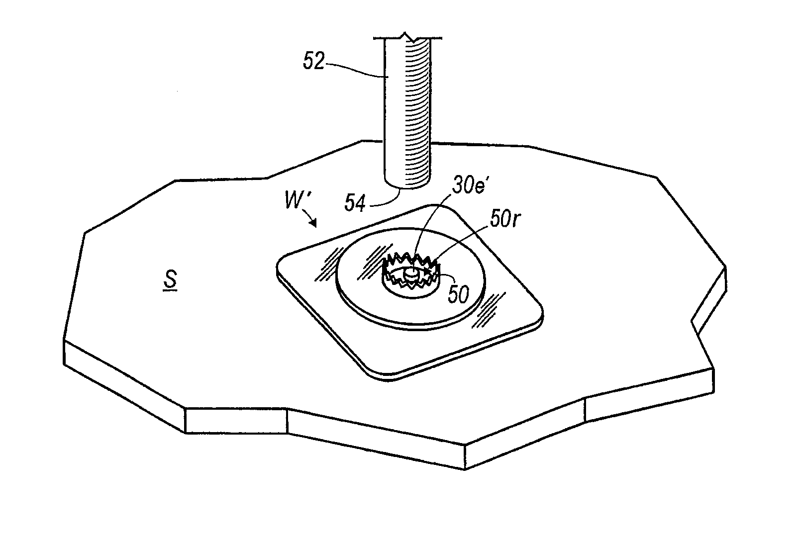
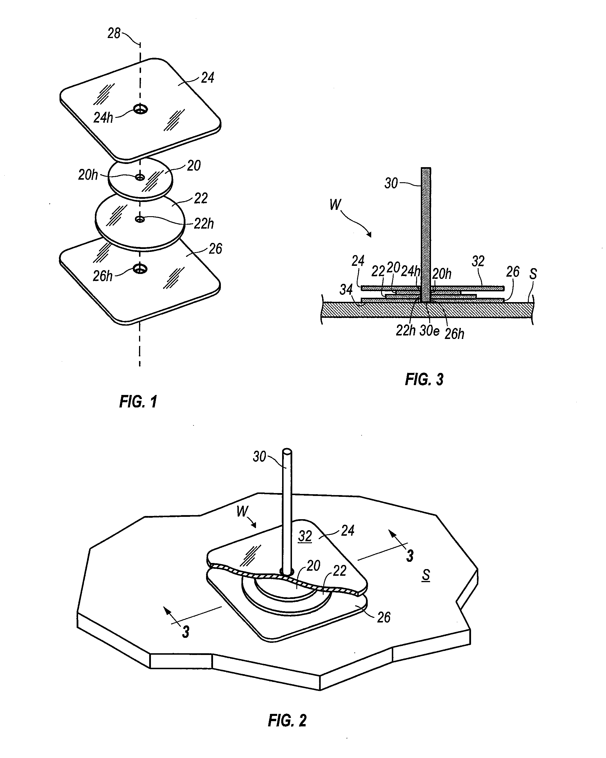
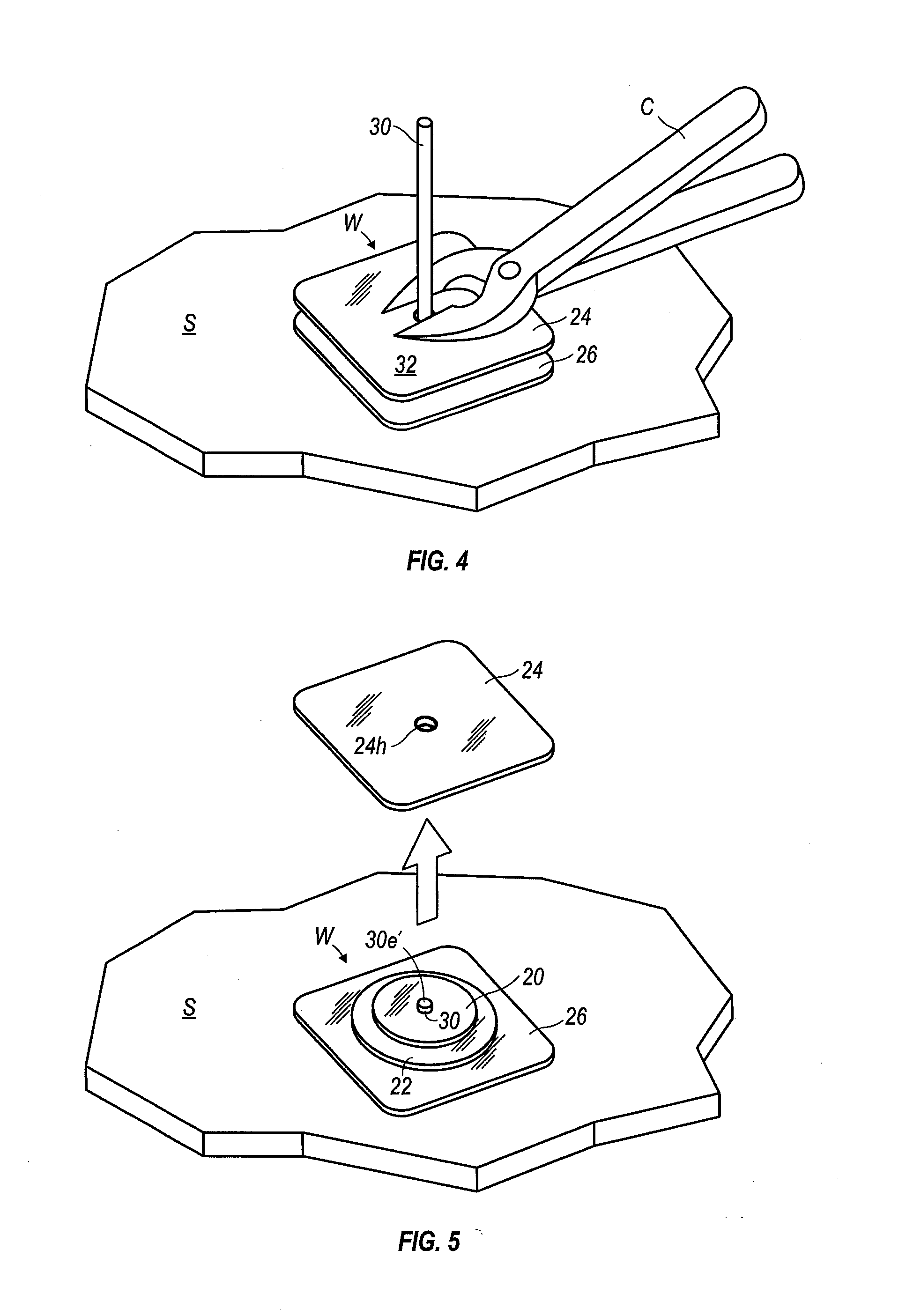
[0014]FIGS. 1-6 show one method of the present invention used to connect two jewelry components during the manufacture of a jewelry item. Referring to FIG. 1, the two components include a first component 20 and a second component 22. In this instance, both components 20, 22 are cylindrical with a cylindrical surface defining a hole 20h, 22h through the respective component. The components 20, 22 are linearly aligned along an axis 28 the centers of the holes 20h, 22h intersecting the axis. The shape of the components is not important to the invention. Moreover, while FIGS. 1-6 show the holes 20h, 22h positioned in the center of the components 20, 22, the holes 20h, 22h may be positioned anywhere within the components 20, 22.

[0015]A first plate 24 and a second plate 26 are positioned on either side of the components 20, 22. Each plate 24, 26 is identically shaped and generally square with rounded corners. Each plate 24, 26 has a cylindrical surface defining a hole 24h, 26h through the...


PUM

PropertyMeasurementUnit
Lengthaaaaaaaaaa
Thicknessaaaaaaaaaa
Diameteraaaaaaaaaa

Abstract

Two plates, corresponding to the diameter of a length of riveting material being used, act as gauges and are placed separately on the top and bottom of at least one components to be made into a jewelry item. The length of material, such as a wire or tubing, is passed through holes in all the components, and the holes of the plates. This allows the jewelry maker to cut the length of material flush with the exposed surface of the plate on the top of the stack. This automatically measures the optimal length of material needed to span the combined thickness of all the components to be riveted together, while providing the desired length exposed at the top and bottom of the stacked pieces, to fashion a properly formed and secure flattened rivet head on each end of the length of material.

Description

CROSS-REFERENCES TO RELATED APPLICATIONS[0001]This original nonprovisional application claims the benefit of the filing date of U.S. provisional application Ser. No. 61 / 840,066, filed Jun. 27, 2013, and U.S. provisional application Ser. No. 61 / 839,183, filed Jun. 25, 2013, each of which is incorporated by reference herein.STATEMENT REGARDING FEDERALLY-SPONSORED RESEARCH OR DEVELOPMENT[0002]Not applicable.BACKGROUND OF THE INVENTION[0003]1. Field of the Invention[0004]The present invention relates to jewelry fabrication. More specifically, the present invention relates to a method of forming a rivet as part of the manufacturing of a jewelry item, either to connect a plurality of jewelry components together or to form a decorative rivet.[0005]2. Description of the Related Art[0006]Rivets are one of the most secure cold connections used in jewelry fabrication, and may also be used for ornamental aspects of a jewelry item. Cutting the precisely desired length of riveting wire or tubing ...

Claims


Application Information

Patent Timeline
IPC IPC(8): A44C27/00
CPCA44C27/00B21J15/041F16B5/04Y10T29/4959Y10T29/53
Inventor YOUNGBLOOD, GWENDOLYN FULLER
Owner YOUNGBLOOD GWENDOLYN FULLER
Why Eureka
Try Eureka