System for thermal management of a vehicle and method for vehicle cold start

a technology for thermal management and vehicles, applied in the direction of engine starters, combustion air/fuel air treatment, lighting and heating apparatus, etc., can solve the problems of increasing exhaust emissions, reducing fuel economy, and increasing engine wear, so as to reduce waste heat, increase the time taken to reach the optimum running temperature, and reduce the effect of fuel consumption

Inactive Publication Date: 2014-12-25
FORD GLOBAL TECH LLC
View PDF4 Cites 27 Cited by
  • Summary
  • Abstract
  • Description
  • Claims
  • Application Information

AI Technical Summary

Benefits of technology

[0001]As internal combustion engines become more fuel efficient, less waste heat is produced, and consequently, the time taken to reach an optimum running temperature increases. This delay in reaching operating temperature may depress fuel economy, increase engine wear and increase exhaust emissions. Additionally, heating systems employed to warm the passenger compartment typically rely on a heater core which is coupled to the coolant jacket of the engine. An increase in engine warm-up time will further result in a delay in warming the passenger compartment, particularly during a cold-start condition.

Problems solved by technology

This delay in reaching operating temperature may depress fuel economy, increase engine wear and increase exhaust emissions.
An increase in engine warm-up time will further result in a delay in warming the passenger compartment, particularly during a cold-start condition.
However, common PCMs may be corrosive to metal, flammable, have low volumetric energy density, may require additional insulation for storage, and the amount of heat stored in the PCM may degrade over time.
Using these systems to warm a passenger compartment may result in large amounts of fuel or electricity diverted from power propulsion systems.
Draining the fuel or battery in this manner may severely restrict the driving range of the vehicle.
However, these systems and methods have similar disadvantages, in that the materials used have low energy density, are highly flammable and prone to losing stored energy over time.

Method used


Image

  • System for thermal management of a vehicle and method for vehicle cold start
  • System for thermal management of a vehicle and method for vehicle cold start
  • System for thermal management of a vehicle and method for vehicle cold start

Examples


Embodiment Construction

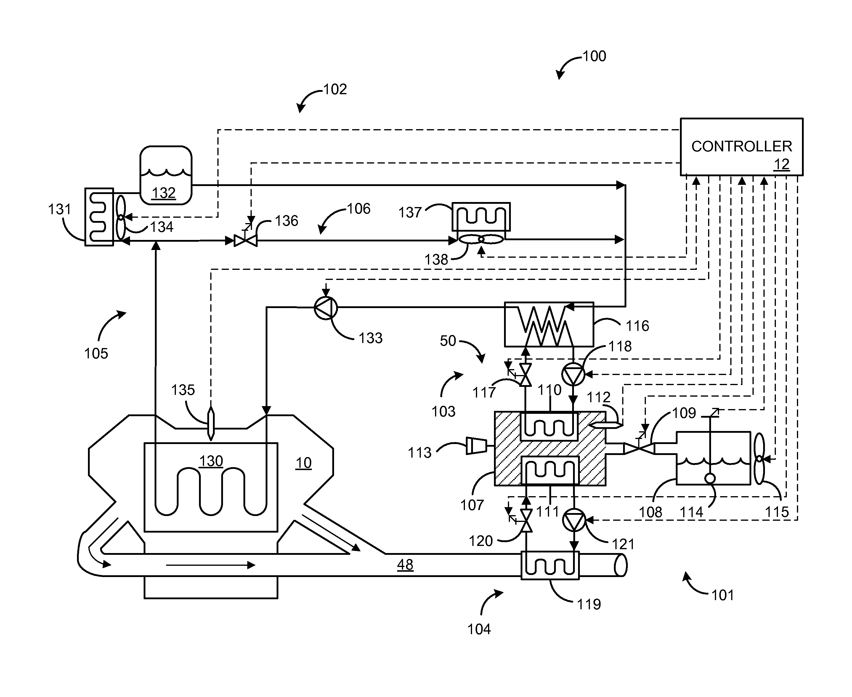
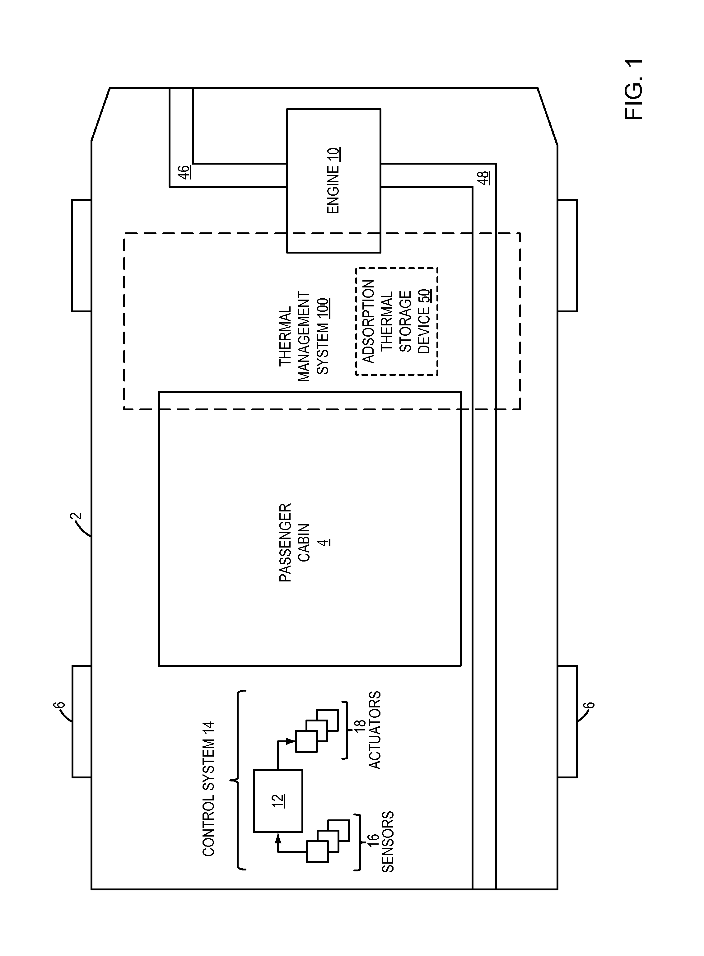
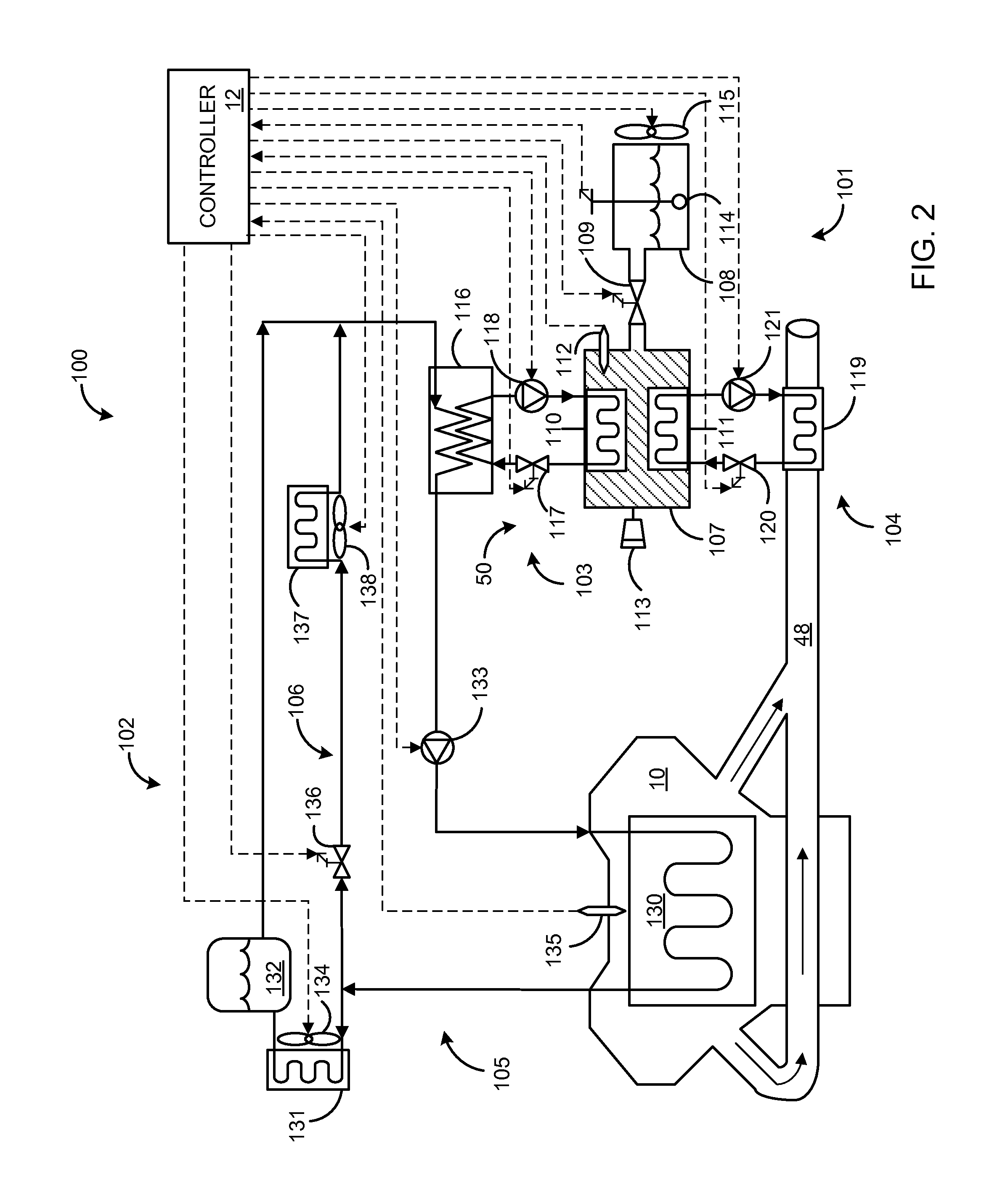
[0014]The following description relates to systems and methods for managing the temperature of a motor vehicle engine and the passenger cabin of the motor vehicle utilizing a thermal management system including an adsorption thermal storage device that stores thermal energy as chemical potential. FIG. 1 shows an example embodiment of a motor vehicle including a thermal management system that may be coupled to the motor vehicle engine, exhaust passage and passenger cabin to manage the heating and cooling of the engine and passenger compartment. FIG. 2 shows a more detailed schematic of the thermal management system, including an adsorption thermal storage device coupled to an adsorber circuit and a coolant circuit. As shown in FIG. 3, the thermal management system may be utilized to enable a method to warm an engine during a cold-start condition. FIG. 4 depicts a high-level flow chart for managing engine and passenger compartment temperatures using the thermal management system. FIG....


PUM


Abstract

A method, comprising during a vehicle engine cold start, opening a first valve coupled between a first container containing an adsorbent and a second container containing an adsorbate, circulating a first fluid through a first conduit coupled to a first heat exchanger located within the first container and a second heat exchanger located outside the first container, and circulating a second fluid through a second conduit coupled to the second heat exchanger. In this way, heat may be generated at the adsorber during a cold start and subsequently transferred to the cooling jacket of the vehicle engine and/or other vehicle compartments, thereby decreasing the warm-up time for the engine.

Description

BACKGROUND AND SUMMARY[0001]As internal combustion engines become more fuel efficient, less waste heat is produced, and consequently, the time taken to reach an optimum running temperature increases. This delay in reaching operating temperature may depress fuel economy, increase engine wear and increase exhaust emissions. Additionally, heating systems employed to warm the passenger compartment typically rely on a heater core which is coupled to the coolant jacket of the engine. An increase in engine warm-up time will further result in a delay in warming the passenger compartment, particularly during a cold-start condition.[0002]To enhance engine warm-up conditions, thermal energy storage devices have been developed to store a gas or liquid medium at high operating temperatures. The most common approach has been to employ a phase change material (PCM) that has been exposed to a solid-liquid or liquid-gas change and heat of fusion to optimize the latent heat storage. However, common P...

Claims


Application Information

Patent Timeline
Patent Type & Authority Applications(United States)
IPC IPC(8): F02N19/04F01N5/02F24V30/00
CPCF01N5/02F02N19/04B60H1/00492B60H1/32014F01P2011/205F01P2037/02F02N19/10F28D20/003Y02E60/14Y02T10/12F28D20/02
Inventor GREINER, CHRISTOPHER MARKTSOU, POYUWANG, KAI
Owner FORD GLOBAL TECH LLC
Why Eureka
Try Eureka