Method for operating an inverter system and inverter system working according to said method

a technology of inverter system and inverter, which is applied in the direction of power conversion system, electrical apparatus, ac-dc conversion, etc., can solve the problems of network parameters that can vary, knowledge is not available, etc., and achieve the effect of enhancing the efficiency of the inverter, reducing the number of energy losses, and adapting the switching frequency

Active Publication Date: 2019-12-31
SIEMENS AG
View PDF15 Cites 1 Cited by
  • Summary
  • Abstract
  • Description
  • Claims
  • Application Information

AI Technical Summary

Benefits of technology

[0021]The advantage of the invention lies in that fact that, by means of the return path, a closed control loop is present for the adaptation of the switching frequency of the inverter, wherein a quality criterion, which describes the instantaneous deviation of a respective interference spectrum from its local (temporally and spatially) allowed limit value is used as a closed-loop control variable.
[0022]For operation in a network with a high short-circuit power, the switching frequency can be adapted, in particular reduced, with the approach proposed here, and consequently the efficiency of the inverter enhanced. For the operator of the inverter it can be worthwhile in economic terms to invest in a powerful network, since fewer energy losses arise and moreover less waste heat has to be dissipated. Moreover a standards-compliant operation can be guaranteed (at least for some of the time) in very low-power networks. To this end the switching frequency is suitably increased automatically, taking account of increased switching losses (which may possibly lead to a derating of the inverter).
[0023]Where the adaptation of the switching frequency leads to a reduction of the switching frequency, a reduction of the switching losses and thus as a rule an improvement in the overall efficiency is achieved, if a network with high quality is available at that moment. Moreover, because of a reduced switching frequency, lower losses result in the power semiconductors of the inverter. This leads to lower semiconductor temperatures and thus on average to an increased lifetime of the inverter, specifically when operated with a mixed load. To this extent the method in accordance with the approach proposed here can also be used explicitly—with a suitable network quality—in order to reduce the thermal load on the inverter in overload situations. Furthermore future guidelines are defining increased requirements for the efficiency under part load. Lowering of the switching frequency is sensible for this in particular and is also able to be used for the network side with the proposed method.
[0024]Advantageous embodiments of the invention are the subject matter of the subclaims. References used in such cases refer to the further embodiment of the main claim by the features of the respective subclaim. They are not to be understood as dispensing with achieving a natural objective protection for the combinations of features of the referenced subclaims. Furthermore, with respect to an arrangement of the claims for a more specific definition of a feature in a subordinate claim, it is to be assumed that a restriction of this sort is not present in the preceding claims in each case. Finally it should be pointed out that the method specified here can also be developed in accordance with the dependent device claims and vice versa.
[0025]In one form of embodiment of the method, voltage and / or current values are determined by means of the data unit or measured voltage values and / or measured current values (output voltage and / or output current) at the network filter by means of a measuring unit functioning as a data unit / data acquisition unit. By means of the evaluation unit a voltage, current or power spectrum is established from said values and this is compared by means of the assessment unit with a corresponding limit spectrum or with a corresponding limit spectrum in each case. The switching frequency is then adapted on the basis of an evaluation of a quality of a current spectrum, voltage spectrum and / or a power spectrum.
[0026]In a further form of embodiment of the method the values determined by means of the data unit or by a measuring unit functioning as a data unit or acquired measured values, namely the acquired measured values at the network-side point of common coupling of the inverter, in particular the measured values (output voltage and / or output current) acquired relating to the current interference emission of the inverter, are acquired with such a high sampling frequency that the entire relevant interference spectrum or indeed at least essentially the entire relevant interference spectrum can be calculated.

Problems solved by technology

As a rule however, this knowledge is not available and moreover the network parameters can vary greatly over time.
Thus the system has to be equipped with attenuation that may not be needed and account has to be taken of corresponding component costs and / or unnecessary switching losses.

Method used


Image

  • Method for operating an inverter system and inverter system working according to said method
  • Method for operating an inverter system and inverter system working according to said method
  • Method for operating an inverter system and inverter system working according to said method

Examples


Embodiment Construction

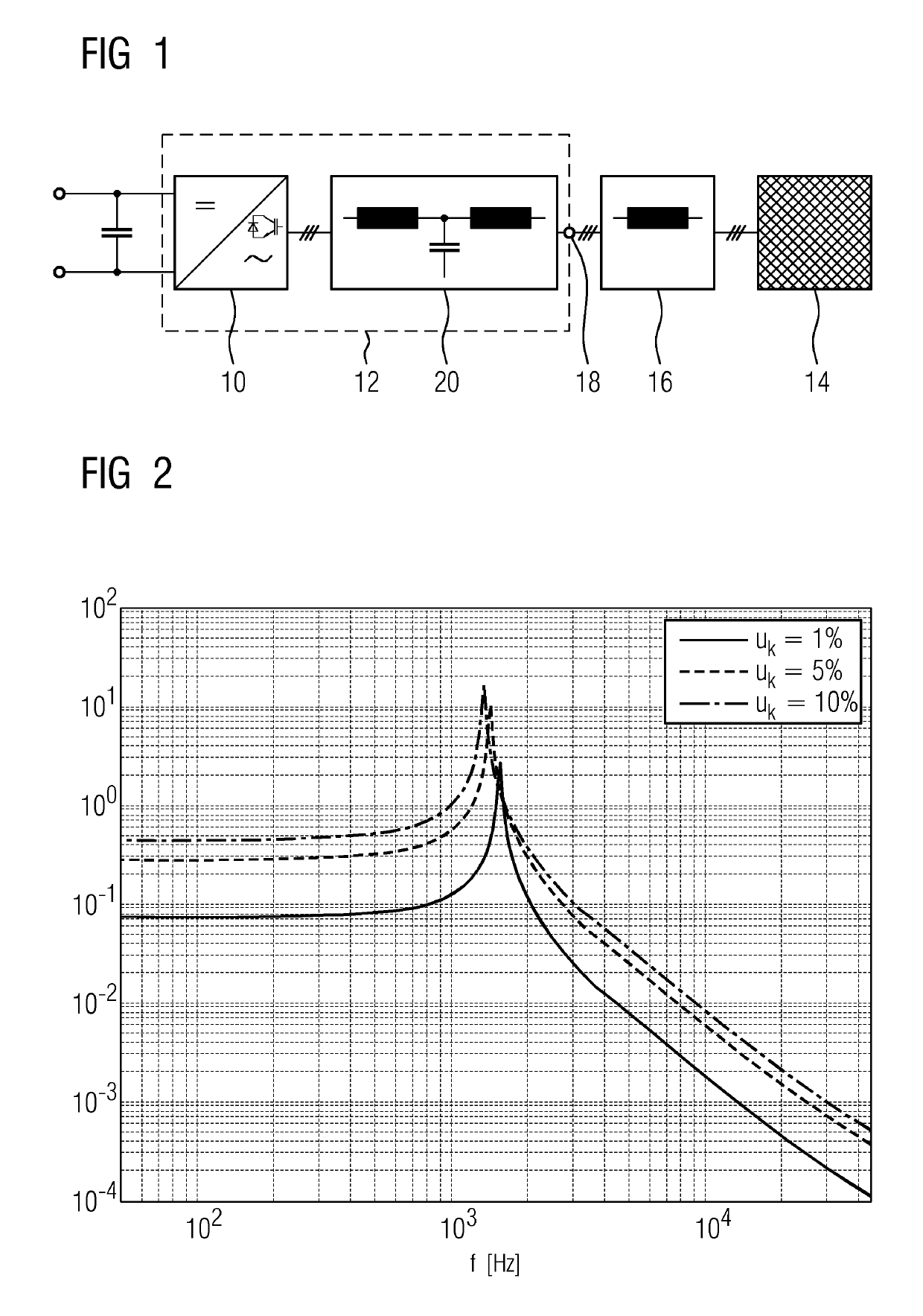
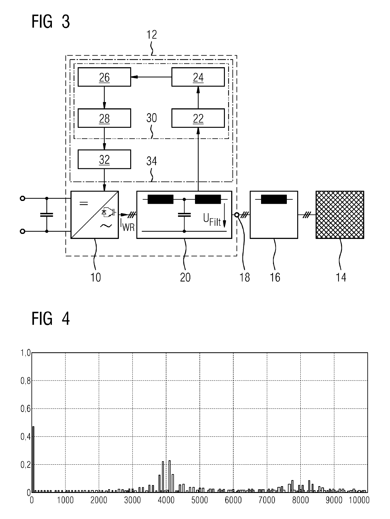
[0043]The diagram in FIG. 1 shows—as already mentioned at the start—an active network-side inverter (network-connected inverter) 10. This is shown as part of an inverter system 12 and will also be referred to for short as an inverter 10 below. Shown on the far right in the diagram in FIG. 1 is the supply network 14. An inductance of the network 14 is shown separately as network inductance 16. The inverter system 12 is connected to the network 14 as a three-phase connection at a network connection point referred to below as the Point of Common Coupling (PCC) 18. A network filter 20 is connected upstream of the inverter 10. Inverter 10 and network filter 20 together form the inverter system 12.

[0044]The diagram in FIG. 2 shows the frequency curve already mentioned at the start of a non-choked LCL filter functioning as a network filter 20 with reference to the transmission function between the output voltage of the inverter 10 and the resulting voltage at the Point of Common Coupling (...


PUM


Abstract

In a method for operating an inverter system and a corresponding inverter system, which includes from the network filter to the inverter, values are determined using the data unit, and a value spectrum of the determined values is determined using an evaluation unit. The value spectrum is compared to a predetermined or predefinable limit spectrum using an assessment unit, and a switching frequency of the inverter can be adapted while in operation by using an adapter unit arranged downstream of the data unit, the evaluation unit and the assessment unit in the return path.

Description

CROSS-REFERENCE TO RELATED APPLICATIONS[0001]This application is the U.S. National Stage of International Application No. PCT / EP2017 / 052852, filed Feb. 9, 2017, which designated the United States and has been published as International Publication No. WO 2017 / 182152 and which claims the priority of European Patent Application, Serial No. 16166228.3, filed Apr. 20, 2016, pursuant to 35 U.S.C 119(a)-(d).BACKGROUND OF THE INVENTION[0002]The invention relates to a method for operating an inverter system and also to an inverter system working according to said method. An inverter system in this case is interpreted as a network-connected inverter together with a network filter connected upstream thereof on the network side.[0003]Active network-connected inverters are typically used for exchange of energy between an AC network and a DC link circuit in each case. They are therefore of great importance both for drive systems, wherein motor inverters use the regulated DC voltage as their inpu...

Claims


Application Information

Patent Timeline
Patent Type & Authority Patents(United States)
IPC IPC(8): H02M1/12H02M7/5395H02M1/44H02M1/00
CPCH02M7/5395H02M1/126H02M1/12H02M2001/0009H02M1/44H02M1/0009
Inventor BENESCH, NORBERTWEIS, BENNO
Owner SIEMENS AG
Why Eureka
Try Eureka