
Solid-state Electronic Apparatus to Provide Reliable Electric Power for Smart Communicating Thermostats

a technology of electronic equipment and smart thermostats, which is applied in the direction of lighting and heating equipment, instruments, heating types, etc., can solve the problems of not providing reliable power, smart communicating thermostats not working properly, and large devices, etc., to achieve reliable power, low cost, and easy installation

Active Publication Date: 2019-11-14
LAU JAMES
View PDF0 Cites 1 Cited by
  • Summary
  • Abstract
  • Description
  • Claims
  • Application Information

AI Technical Summary

Benefits of technology

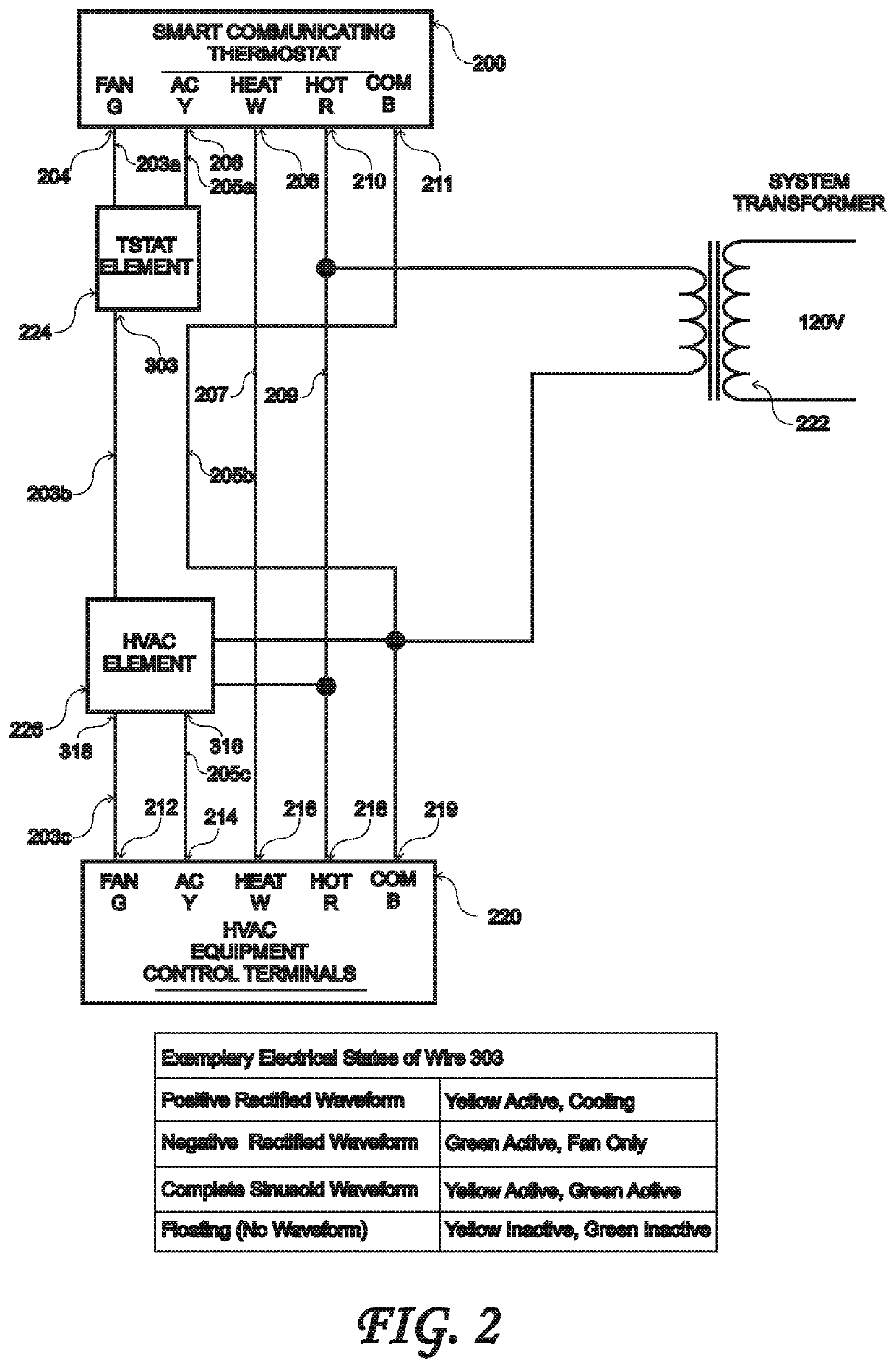
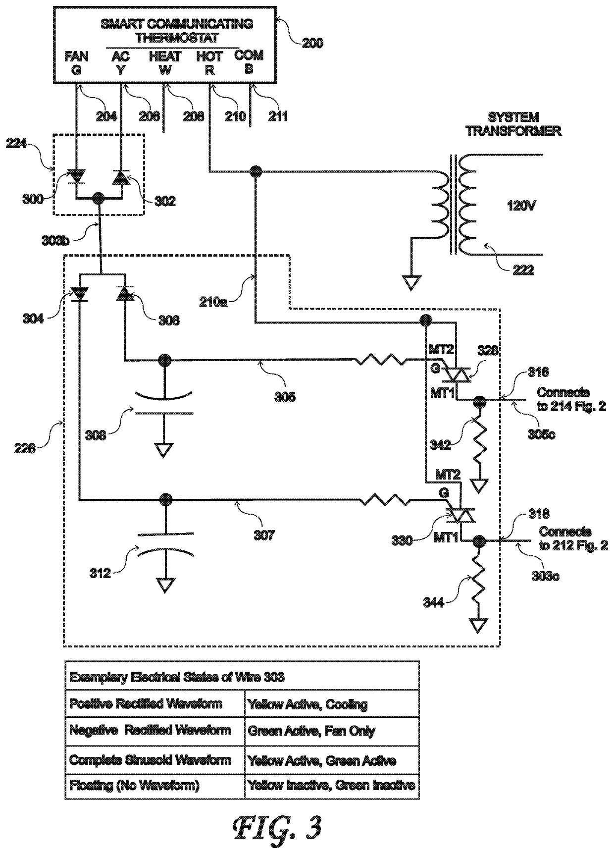
The present invention is a solid-state common-wire adapter that solves the problem of providing reliable power to Smart Communicating Thermostats in buildings without the need for a common wire. The invention uses solid state electronic devices that are not limited to a rated number of operations, reducing power draw and waste heat for longer operation. The invention is easy to install and provides consistent power, customer comfort, and safety at a low cost. The invention also allows for the re-purposing of one of the wires in the wire bundle from the HVAC control terminals to the thermostat to be used to carry the common signal from the system transformer to the thermostat, when the common wire is not present in the bundle. Overall, the invention provides a small, low-cost, reliable, and easy-to-install solution for adding a“common wire” function to any thermostat location.

Problems solved by technology

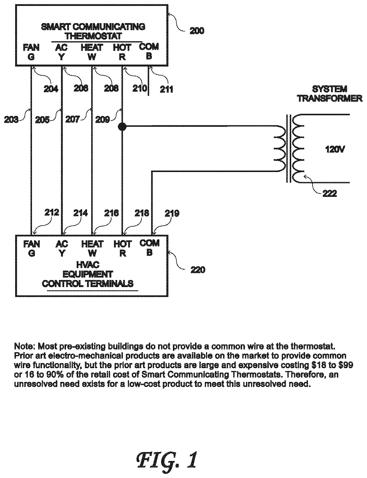
Pre-existing conventional thermostats do not require a common wire, and pre-existing wiring harnesses often do not provide a common wire to provide reliable power for smart communicating thermostats used to control Heating, Ventilation, Air Conditioning (HVAC) systems.
Prior art electro-mechanical devices are available in the market to provide a common wire at the thermostat, but these devices are large and expensive and can cost from $18 to $99 per unit which is 16 to 90% of the cost of a smart communicating thermostat.
Due to the larger size and expense, smart communicating thermostat manufacturers are attempting to design around the problem of no common wire at the thermostat using power stealing, but this has caused numerous problems with loss of power and reliability causing smart communicating thermostats not to function properly.
This power stealing creates numerous problems for the HVAC system.
First, the device from which the power is drawn can activate unintentionally or not activate.
For example, the AC compressor can be turned on unintentionally when there is no call for cooling.
The HVAC system can unintentionally activate a heating cycle, or the fan can come on when there is no call for the fan.
This can cause building occupants to be uncomfortably hot with no AC during summer or cause building occupants to be uncomfortably cold with no heating during winter or cause water in a plumbing system to freeze causing water damage in the building.
Maintaining a lower heater ventilation fan speed often results in increased heat soak within the central heating unit and the portion of the heat generated by the heat source not delivered to conditioned space is lost to the environment.
The heat loss increases the central heating unit operational time consuming more energy.
Further, the amount of heat soak increases as the central heating unit is operated for longer periods of time leaving significantly more unrecovered energy and higher temperatures (i.e., 260 to 470 degrees Fahrenheit) in the heat exchanger after the heater ventilation fan is turned off.
In most heating systems a significant portion of this unrecovered heating energy is wasted and lost to the environment after the heat source and the heater ventilation fan are tuned off.
When the cooling source is de-energized, there is a significant amount of cold water condensed onto the evaporator coil which is not used to deliver sensible cooling capacity to the conditioned space.
This sensible cooling capacity is lost to the environment after the cool source and the cooling ventilation fan are tuned off.
This increases the cooling system operational time and energy use.
Known heat pump and hydronic systems do not provide a fan-on delay.
Nor do heat pump and hydronic systems provide a heating fan-off time delay due to lower heat exchanger temperatures of 130 to 180 degrees Fahrenheit, which are 2 to 3 times lower than gas furnace heat exchanger temperatures.
During the start-up period there is no useful heating delivered by the ventilation air which can waste fan energy and cause thermal comfort issues for building occupants.
When the heat source is de-energized there is a significant amount of heating energy left in the heating coil which is not used to deliver heating capacity to the conditioned space, and this heating capacity is lost to the environment after the heat source and the heating ventilation fan are tuned off.
The heat loss increases the heat pump, electric resistance, or hydronic heating system operational time and energy use.
All prior art electro-mechanical products are expensive and some are designed for specific thermostats.
Prior art electro-mechanical designs are expensive to manufacture due to the costs associated with the electro-mechanical relays, both in the cost of the physical part, and also in the cost associated with manufacturing costs to manually install through-hole relays on circuit boards during manufacturing.
This package adds to the cost of the overall solution.
Prior art products do not provide a small, low-cost, and reliable solution to meet the unresolved need of providing a common wire and reliable power for smart communicating thermostats.

Method used


Image

  • Solid-state Electronic Apparatus to Provide Reliable Electric Power for Smart Communicating Thermostats
  • Solid-state Electronic Apparatus to Provide Reliable Electric Power for Smart Communicating Thermostats
  • Solid-state Electronic Apparatus to Provide Reliable Electric Power for Smart Communicating Thermostats

Examples


Embodiment Construction

[0084]The following description is of the best mode presently contemplated for carrying out the invention. This description is not to be taken in a limiting sense, but is made merely for the purpose of describing one or more preferred embodiments of the invention. The scope of the invention should be determined with reference to the claims.

[0085]FIG. 1 shows prior art thermostat wiring when only 4 wires are available in the wiring harness. This case is prevalent in existing buildings which were built before Smart Communicating Thermostats were available. Most thermostats prior to Smart Communicating Thermostats simply connected the Hot R terminal 210 to the appropriate output based on whether the thermostat was set for heating or cooling. For cooling, the standard thermostat connects the Hot R terminal 210 to both the Fan G terminal 204 and the AC Y terminal 206. This activates the compressor and the system fan. For heating, the thermostat connects the Hot R terminal 210 to the Heat...


PUM


Abstract

A solid-state adapter provides a common-wire functionality to an HVAC system including four wire connections between a thermostat and HVAC equipment The adapter may include an embodiment of an efficient fan controller to provide a fan-off delay based on the duration of a heating cycle or the duration of a cooling cycle where the duration includes at least one duration selected from the group consisting of: a heating on time, a heating off time, a cooling on time, and a cooling off time. The solid-state common-wire adapter uses a TRIAC, capacitor and load resistor to provide a small, low-cost and reliable electronic device which repurposes the existing wiring harness to add a common wire functionality where previously one did not exist. The common-wire function is required in many buildings with pre-existing low-voltage 4-wire electrical harnesses in order to provide continuous and reliable power to Smart Communicating Thermostats that connect to the internet using a wireless Ethernet network officially referred to as the IEEE 802.11 standard.

Description

CROSS-REFERENCE TO RELATED APPLICATIONS[0001]The present application claims the priority of U.S. Provisional Patent Application Ser. No. 61 / 324,229 filed Apr. 14, 2010, and is a Continuation In Part of U.S. patent application Ser. No. 13 / 085,119 filed Apr. 12, 2011, and is a Continuation In Part of U.S. patent application Ser. No. 13 / 427,542 filed Mar. 22, 2012, and is a Continuation In Part of U.S. patent application Ser. No. 14 / 168,503 filed Jan. 30, 2014, and is a Continuation In Part of U.S. patent application Ser. No. 15 / 144,806 filed May 2, 2016, and claims the priority of U.S. Provisional Patent Application Ser. No. 62 / 670,134 filed May 11, 2018, which applications are incorporated in their entirety herein by reference.BACKGROUND OF THE INVENTION[0002]Pre-existing conventional thermostats do not require a common wire, and pre-existing wiring harnesses often do not provide a common wire to provide reliable power for smart communicating thermostats used to control Heating, Vent...

Claims


Application Information

Patent Timeline
Patent Type & Authority Applications(United States)
IPC IPC(8): F24F11/30F24D19/10G05D23/19F24F11/88F24F11/58F24F11/65G05B15/02
CPCF24F2221/54F24F11/58F24F11/30F24F11/65F24F2110/10F24D19/1084F24F11/88F24F2140/60G05B15/02G05D23/1917
Inventor WALSH, JOHNMOWRIS, ROBERT J.
Owner LAU JAMES
Learn More