System and method for determining weld travel speed

a technology of travel speed and system, applied in the field of welding operations, can solve the problems of inability to provide real-time feedback and easy errors

Active Publication Date: 2014-12-25
ILLINOIS TOOL WORKS INC
View PDF13 Cites 64 Cited by
  • Summary
  • Abstract
  • Description
  • Claims
  • Application Information

AI Technical Summary

Benefits of technology

[0005]In one embodiment, a welding system includes one or more sensors configured to provide a first indication correspond to a welding arc at a first time and to provide a second indication correspond to the welding arc at a second time. The welding system also includes processing circuitry configured to receive the first indication, to receive the second indication, and to determine a weld travel speed based on a weld length of the workpiece and a difference between the first and second times.
[0006]In another embodiment, a method for determining

Problems solved by technology

Unfortunately, such manual methods of determining the weld travel speed may use a person in addition to the welding op

Method used


Image

  • System and method for determining weld travel speed
  • System and method for determining weld travel speed
  • System and method for determining weld travel speed

Examples


Embodiment Construction

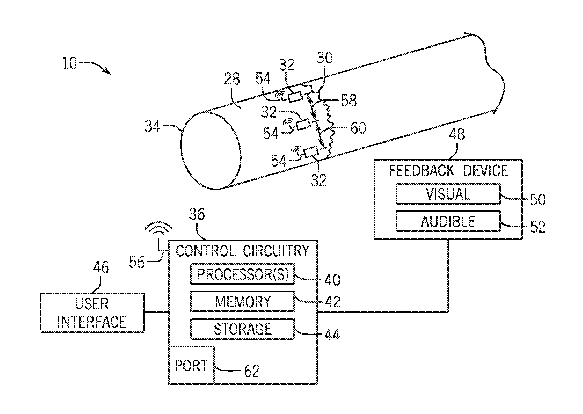
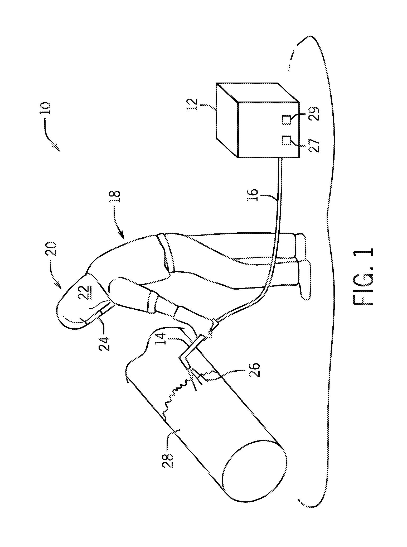
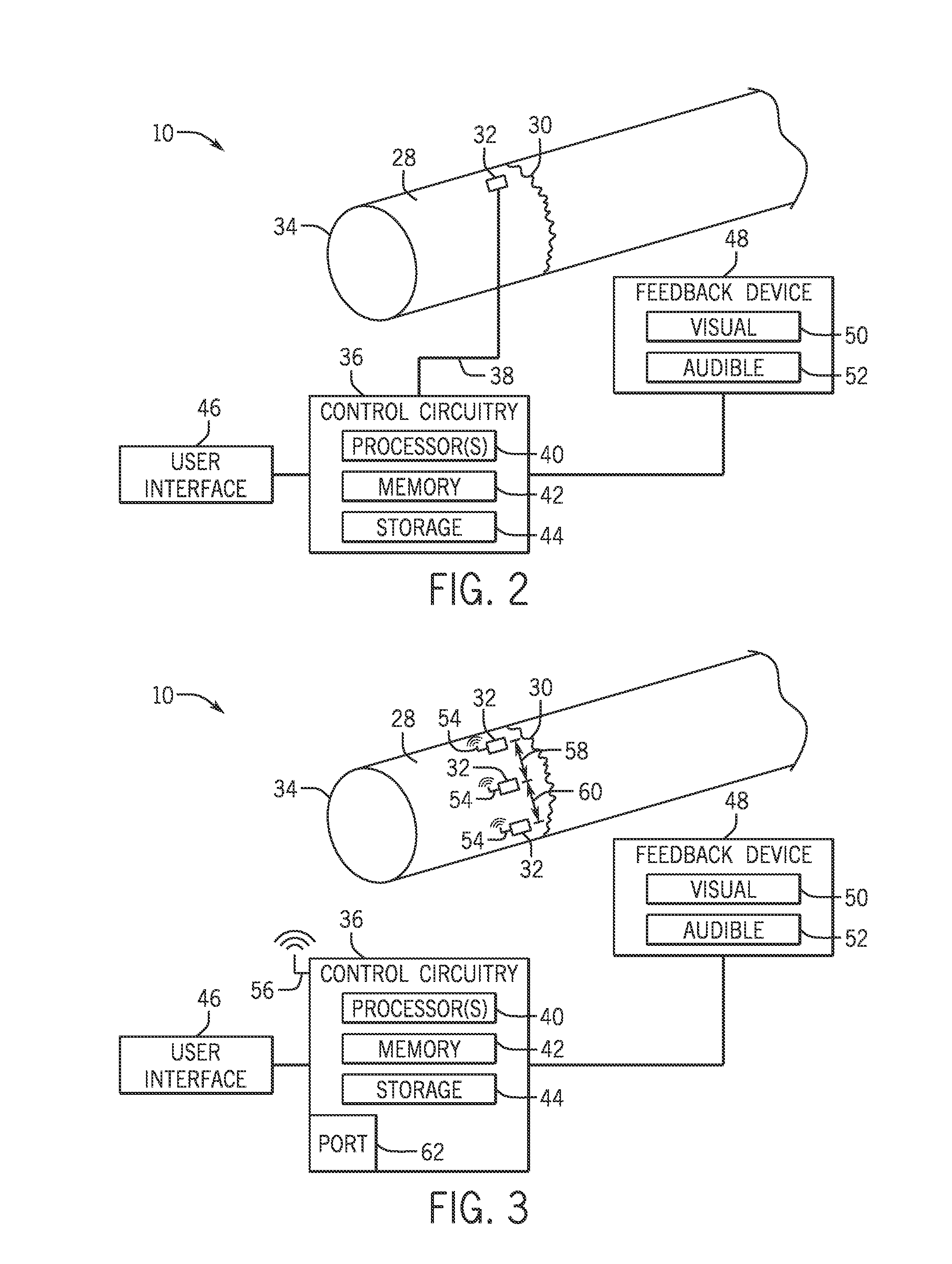
[0018]Embodiments of the present invention may be used in any application where weld travel speed may be determined. For example, FIG. 1 illustrates an arc welding system 10 in which the weld travel speed may be determined. As depicted, the arc welding system 10 may include a power supply system 12 that generates and supplies welding power to an electrode 14 via a conduit 16. In the arc welding system 10, a direct current (DC) or alternating current (AC) may be used along with the consumable or non-consumable electrode 14 to deliver current to the point of welding. In such a welding system 10, an operator 18 may control the location and operation of the electrode 14 by positioning the electrode 14 and triggering the starting and stopping of the current flow. As illustrated, a helmet assembly 20 is worn by the welding operator 18. The helmet assembly 20 includes a helmet shell 22 and a lens assembly 24 that may be darkened to prevent or limit exposure to the light generated by a weld...


PUM

PropertyMeasurementUnit
Lengthaaaaaaaaaa
Speedaaaaaaaaaa
Electric potential / voltageaaaaaaaaaa

Abstract

A system and method for determining weld travel speed. In one example, a welding system includes one or more sensors configured to provide a first indication correspond to a welding arc at a first time and to provide a second indication correspond to the welding arc at a second time. The welding system also includes processing circuitry configured to receive the first indication, to receive the second indication, and to determine a weld travel speed based on a weld length of the workpiece and a difference between the first and second times.

Description

[0001]This application is a Non provisional patent application of U.S. Provisional Patent Application No. 61 / 837,905, entitled “SYSTEM AND METHOD FOR DETERMINING WELD TRAVEL SPEED”, filed Jun. 21, 2013, which is incorporated herein by reference in its entirety.BACKGROUND[0002]The invention relates generally to welding operations and, more particularly, to systems and methods for determining weld travel speed.[0003]Welding is a process that has increasingly become utilized in various industries and applications. Such processes may be automated in certain contexts, although a large number of applications continue to exist for manual welding operations. In both cases, such welding operations rely on a variety of types of equipment to ensure the supply of welding consumables (e.g., wire feed, shielding gas, etc.) is provided to the weld in appropriate amounts at the desired time.[0004]A quality of a weld on a workpiece may depend on a number of factors, some of which may be controlled b...

Claims


Application Information

Patent Timeline
IPC IPC(8): B23K9/095
CPCB23K9/0956B23K9/0953B23K9/0282B23K2101/06
Inventor LUO, JYI-JIINNELLI, CHRISTOPHER J.HOLVERSON, TODD EARLMULROY, ANDREW PATRICK
Owner ILLINOIS TOOL WORKS INC
Why Eureka
Try Eureka