
Method of leakage current and borehole environment correction for oil based mud imager

a technology of oil mud imager and leakage current, which is applied in the field of electric resistivity well logging, can solve problems such as affecting the accuracy of resistivity measuremen

Inactive Publication Date: 2014-12-25
LIU YUE +6
View PDF4 Cites 11 Cited by
  • Summary
  • Abstract
  • Description
  • Claims
  • Application Information

AI Technical Summary

Benefits of technology

The patent describes a method for measuring the resistivity of formation surrounding a borehole using a logging tool. The method involves deploying a sensor pad in the borehole and measuring the total current entering into the current electrodes. The sensor pad has a pair of current electrodes and a pair of voltage electrodes, and an internal capacitive impedance is measured between the current electrodes and the sensor pad. The method also includes computing the external capacitive impedance between the current electrodes and the formation. The external capacitive impedance is used to compute a geometric factor that is used to calculate the resistivity of the formation. The method can be calibrated based on the internal and external capacitive impedances. The technical effect of the patent is to provide a reliable and accurate method for measuring the resistivity of formation surrounding a borehole.

Problems solved by technology

The leakage currents and bypass currents are parasitical and may affect accuracy of resistivity measurement.

Method used


Image

  • Method of leakage current and borehole environment correction for oil based mud imager
  • Method of leakage current and borehole environment correction for oil based mud imager
  • Method of leakage current and borehole environment correction for oil based mud imager

Examples


Embodiment Construction

[0057]Referring now to FIGS. 4 through 11, exemplary embodiments of the present invention are depicted. It will be understood by one skilled in the art that the present invention can be well suited with an oil-based mud imager or similar imaging device. It will also be understood by one skilled in the art that the present invention can be used with any kind of subterranean drilling operation, either offshore or onshore.

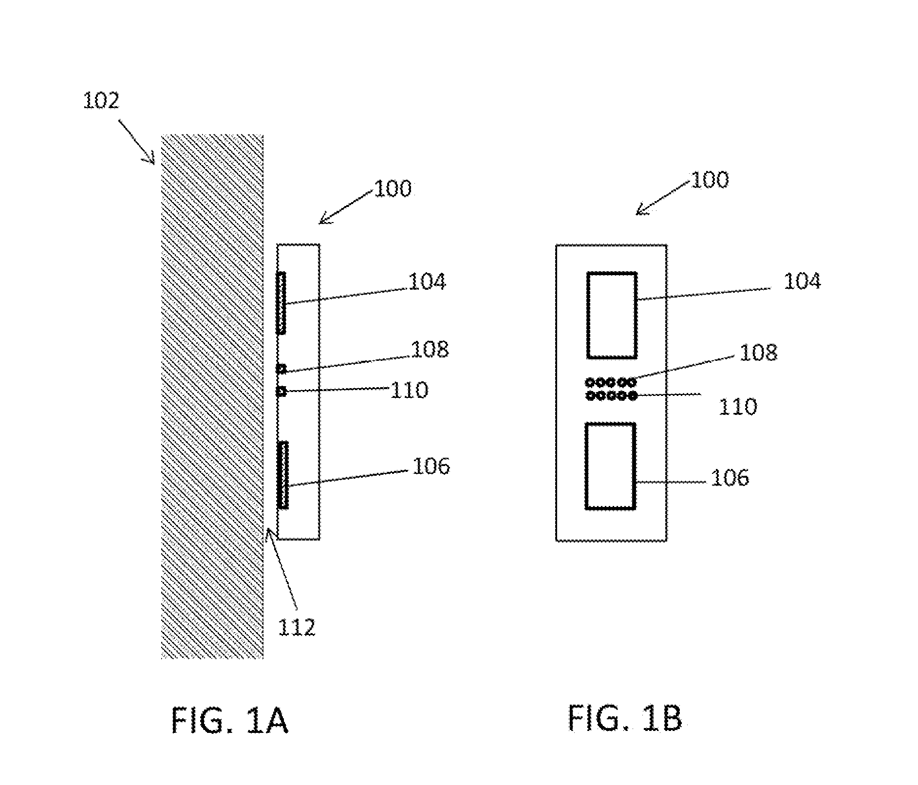
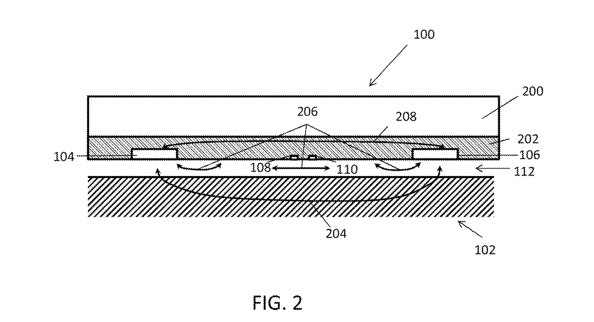
[0058]FIG. 4 shows a cross-sectional view of the sensor pad 100 with improved measurement circuits and structure designs according to some embodiments of the present invention. The sensor pad 100 can include a pair of current electrodes 104 and 106 and a pair of voltage electrodes 108 and 110. The current electrodes 104 and 106 and voltage electrodes 108 and 110 can be covered with an insulating material 400 and shielded from the metal body 200 of the sensor pad 100. The size of the insulating material 400 can vary. To measure the resistivity of the formation 102, two...


PUM


Abstract

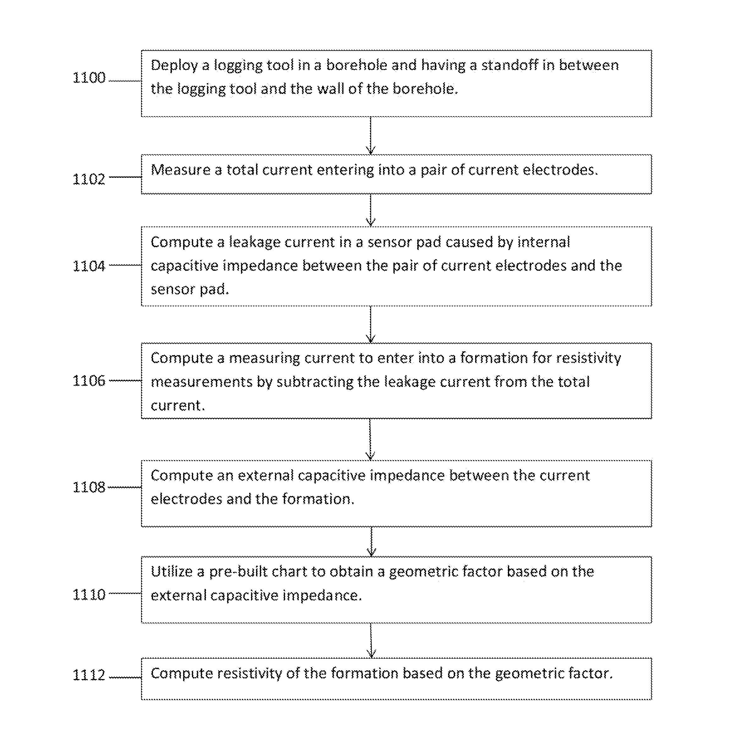
A correction method for resistivity measurements of formation surrounding a borehole includes deploying a logging tool in the borehole and having a standoff in between the logging tool and the wall of the borehole, measuring a total current entering into the pair of current electrodes, computing a leakage current in the sensor pad caused by an internal capacitive impedance between the pair of current electrodes and the main body of the sensor pad, computing a measuring current to enter into the formation for the resistivity measurements by subtracting the leakage current from the total current, computing an external capacitive impedance between the current electrodes and the formation, utilizing a pre-built chart to obtain a geometric factor based on the external capacitive impedance, and computing resistivity of the formation based on the geometric factor.

Description

FIELD OF THE INVENTION[0001]The present invention relates generally to the field of electrical resistivity well logging. More particularly, the invention relates to an apparatus and a method for determining the formation resistivity using electrical methods, including leakage current and borehole environment correction for oil based mud micro-resistivity imager.BACKGROUND OF THE INVENTION[0002]The use of electrical measurements for gathering of downhole information, such as logging while drilling (“LWD”), measurement while drilling (“MWD”), and wireline logging system, is well known in the oil industry. Such technology has been utilized to obtain a great quantity of geological information regarding conditions and parameters encountered downhole. It is important to determine geological information with a high degree of accuracy for drilling efficiency. For example, as known in the prior art, the formation containing hydrocarbon (such as crude oil or gas) usually has higher resistivit...

Claims


Application Information

Patent Timeline
IPC IPC(8): G01V3/20G01V3/38
CPCG01V3/38G01V3/20
Inventor LIU, YUEZHAO, QIHUIBAI, QINGJIELU, YUZHOUWANG, ZHONGWU, SUMINGLIU, CE
Owner LIU YUE
Learn More