Antenna with fifty percent overlapped subarrays

a phased array and subarray technology, applied in the direction of antennas, linear waveguide fed arrays, electrical equipment, etc., can solve the problems of grating lobes, unsatisfactory implementation costs, and reduced requirements for phase control modules/receivers

Active Publication Date: 2014-12-25
APTIV TECH LTD
View PDF7 Cites 44 Cited by
  • Summary
  • Abstract
  • Description
  • Claims
  • Application Information

AI Technical Summary

Problems solved by technology

Electronic scanning or digital beam-forming using an array of antenna elements or radiating elements is known, but is often undesirably costly to implement since phase control modules and / or receivers for each radiating element are typically required.
This reduces the number of phase control modules / receivers required, but undesirably leads to grating lobes.
However, acceptable grating lobe suppression is difficult to achieve for limited scan antennas that use sub-arrays.

Method used


Image

  • Antenna with fifty percent overlapped subarrays
  • Antenna with fifty percent overlapped subarrays
  • Antenna with fifty percent overlapped subarrays

Examples


Embodiment Construction

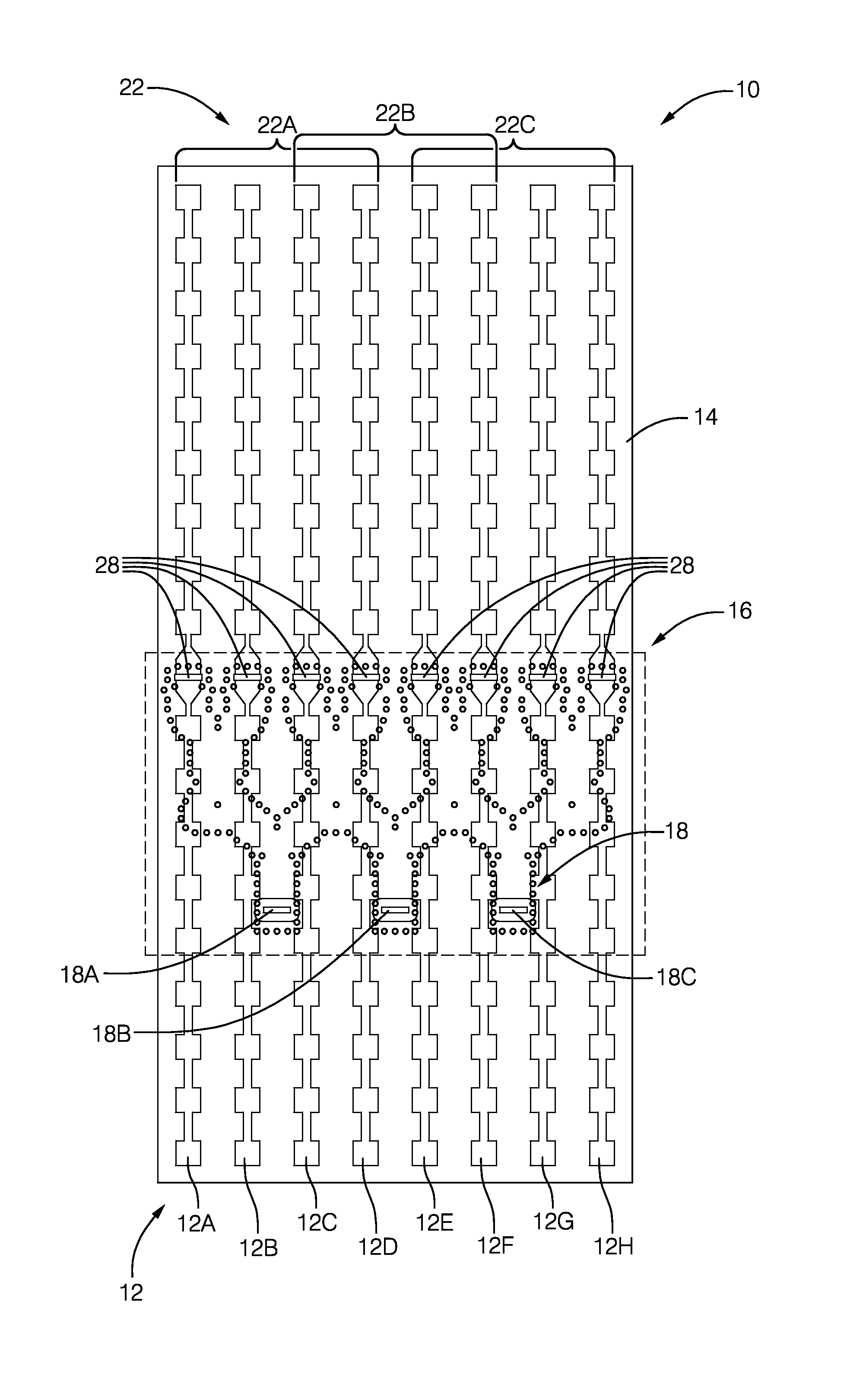
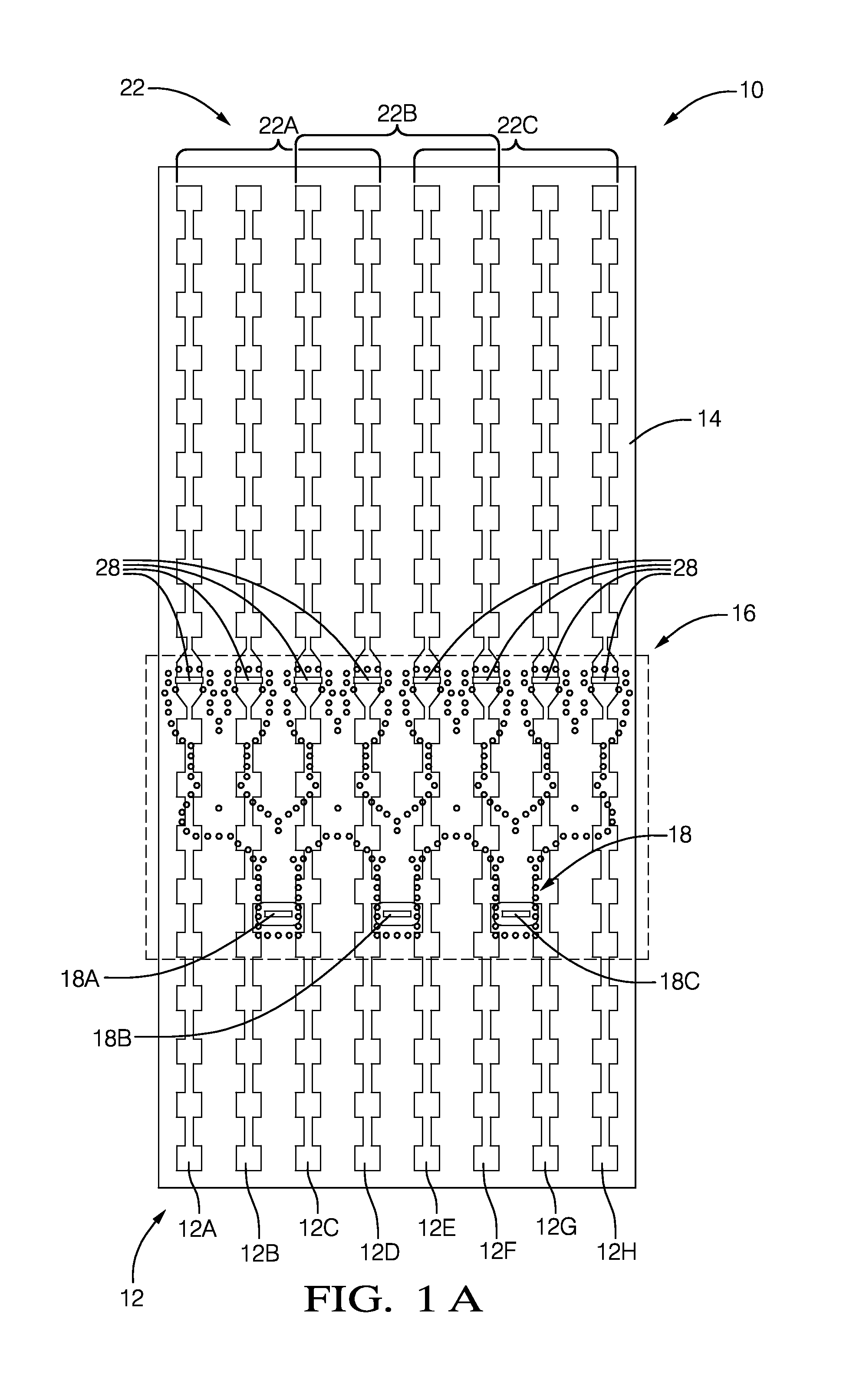
[0013]FIG. 1A illustrates a top view of a non-limiting example of a phased array antenna, hereafter the antenna 10. In general, the antenna 10 and variations thereof described herein are suitable for use by a radar system (not shown), for example as part of an object detection system on a vehicle (not shown). By way of example and not limitation, the antenna 10 described herein may be part of object detection system on a vehicle that combines signals from a camera and a radar to determine the location of an object relative to a vehicle. Such an integrated radar and camera system has been proposed by Delphi Incorporated, with offices located in Troy, Mich., USA and elsewhere that is marketed under the name RACam, and is described in United States Published Application Number 2011 / 0163916 entitled INTEGRATED RADAR-CAMERA SENSOR, published Jul. 7, 2011 by Alland et al., the entire contents of which are hereby incorporated herein by reference. Sizes or dimensions of features of the ante...


PUM


Abstract

An antenna suitable for use as a phased array antenna of a radar system. The antenna includes a plurality of radiating elements, and a substrate integrated waveguide (SIW) configured to form a feed network to couple energy from a plurality of inputs to the radiating elements. The feed network includes over-moded waveguide couplers configured so energy propagates through an over-moded section in multiple modes, TE10 and TE20 modes for example. The feed network also defines sub-arrays configured such that half of the radiators of a sub-group are shared with an adjacent sub-group of an adjacent sub-array, i.e. the sub-arrays are configured to have 50% overlap. Preferably, the feed-network is formed about a single layer of substrate material.

Description

TECHNICAL FIELD OF INVENTION[0001]This disclosure generally relates to a phased array antenna of a radar system, and more particularly relates to an antenna with multiple sub-arrays of grouped radiating elements coupled to inputs by a substrate integrated waveguide (SIW) type feed network that includes over-moded waveguide couplers that allow half (50%) of the radiating elements of one sub-array to overlap with radiating elements of another sub-array.BACKGROUND OF INVENTION[0002]Radar systems often require an antenna with many elements to provide the required gain, beam-width, etc. Electronic scanning or digital beam-forming using an array of antenna elements or radiating elements is known, but is often undesirably costly to implement since phase control modules and / or receivers for each radiating element are typically required. For limited scan, a phased array antenna may be formed by grouping the radiating elements into sub-arrays. This reduces the number of phase control modules / ...

Claims


Application Information

Patent Timeline
Patent Type & Authority Applications(United States)
IPC IPC(8): H01Q21/00
CPCH01Q21/0037H01Q13/206H01Q21/0068H01Q21/068H01Q21/22
Inventor SHI, SHAWN
Owner APTIV TECH LTD
Why Eureka
Try Eureka