
Method and Apparatus for a Self-Focusing Camera and Eyeglass System

a self-focusing camera and eyeglass technology, applied in closed circuit television systems, television systems, instruments, etc., can solve the problems of decreasing camera cost, achieve the effects of improving the quality of reconstructed long-range 3-d, increasing the base distance between two plenoptic cameras, and facilitating the use of the system

Active Publication Date: 2014-12-25
TRACKTHINGS
View PDF14 Cites 14 Cited by
  • Summary
  • Abstract
  • Description
  • Claims
  • Application Information

AI Technical Summary

Benefits of technology

This patent describes an apparatus that allows a smart phone to have two plenoptic cameras. These cameras can be placed at different distances from the phone to increase the baseline distance between them. This information can be used to improve the quality of reconstructed long range 3-D images or video. The cameras can also be attached to eyeglasses or mated to a surface on the phone. The cameras can be placed at various distances to analyze the depth of images, and the images can be shared within the system. This technology offers greater flexibility and accuracy in analyzing depth information.

Problems solved by technology

However, as the cost of the camera has been decreasing, a second camera has been placed on the same side as the display screen.

Method used


Image

  • Method and Apparatus for a Self-Focusing Camera and Eyeglass System
  • Method and Apparatus for a Self-Focusing Camera and Eyeglass System
  • Method and Apparatus for a Self-Focusing Camera and Eyeglass System

Examples


Embodiment Construction

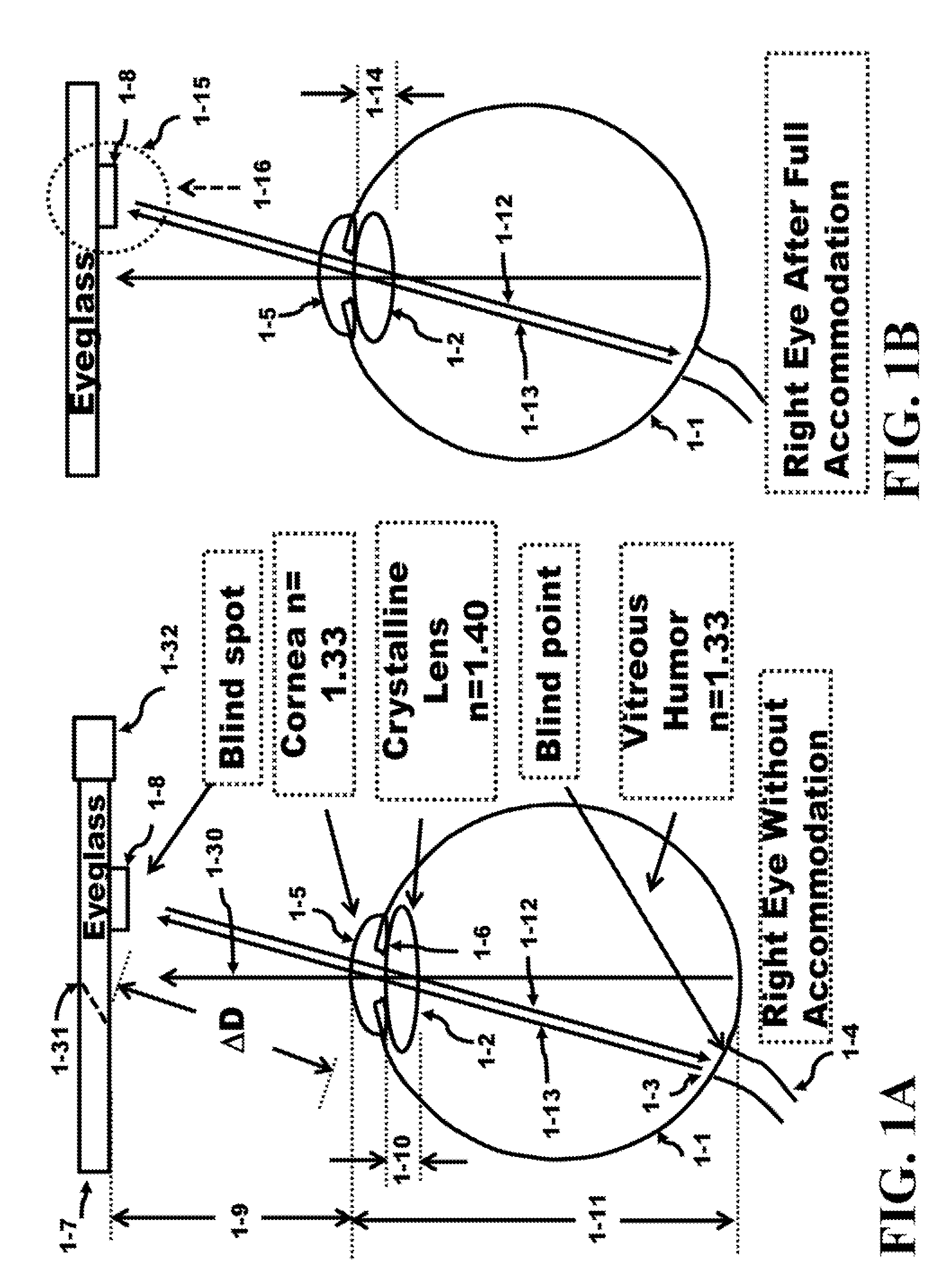
[0078]FIG. 1A presents a pictorial of the right eye, an eyeglass, a source of electromagnetic radiation, a sensor of electromagnetic radiation, and components of the right eye. The eye measuring system 1-33 comprises a source and a detector 1-8 of electromagnetic radiation to measure the total flight path of the electromagnetic radiation propagation. The electromagnetic radiation exits the source propagates in the right eye 1-1 towards the blind point 1-3 and bounces off the blind point. The incident electromagnetic radiation was reflected from the blind point on the back surface of the eye 1-1 offering at least two advantages; 1) the position of the transparent material 1-19 is located at what is known as being in the blind spot of the eye, a physical location outside the eye where the eye cannot sense the object; and 2) the incident radiation reflects off the surface of the blind point 1-3 on the backside of the eye 1-1 and since this blind point 1-3 does not have light gathering ...


PUM


Abstract

An involuntary action adjusted by the accommodation of the crystalline lens of the eye provides the data to the embedded algorithm to get the new image. Instead of the user performing a voluntary action to control the embedded algorithm, an involuntary action by the user is used to control the embedded algorithm allowing the user to automatically adjust the Plane of Depth (POD) for a Light Field Photograph (LFP) image or an eyeglass image. The adjustment of eyeglass image is used by an accommodation system to control the mechanical system of lenses in an eyeglass to automatically focus the glasses over a range of PODs. In addition, a voluntary far / near button can be used manually to adjust the POD for both the LFP image and the eyeglass adjustment. The variation of the crystalline thickness to adjust the focus of nearby and distant objects is called accommodation.

Description

BACKGROUND OF THE INVENTION[0001]Portable wireless units (cellphones, smartphones, etc.) are offering the user with easy access to others users via multimedia, text, voice, images or videos. Similarly, the wireless systems interconnect to the Internet to store these components on a server. The camera on these wireless systems have been employed to store and / or send multimedia, photos and video for postings on the web, sharing with other users, or for personal perusal for a later date.[0002]The camera typically shows an image that is focused at a particular depth. The other Plane of Depths (POD) in the Field of View (FOV) are out of focus. This photograph has been the mainstream of images and forms the basis of videos where one image after another is shown in sequence to present a moving image to the viewer or user. The focus of depth set by the photographer or movie producer and the user basically has no input to seeing the image or video at another POD.[0003]Some smart phones provi...

Claims


Application Information

Patent Timeline
IPC IPC(8): H04N7/18
CPCH04N7/18H04N13/383G06F3/013
Inventor GABARA, THADDEUS JOHN
Owner TRACKTHINGS
Learn More