Vehicle Display Device with Movement Compensation

a technology of vehicle display and movement compensation, which is applied in the direction of television systems, instruments, image enhancement, etc., can solve the problems of difficulty in identifying the arrow clearly with the actual turning point, inability to compensate for proper surface motion, and inability to achieve the effect of facilitating vehicle navigation, large compensation of proper motion, and convenient vehicle navigation

Inactive Publication Date: 2014-12-25
DAIMLER AG
View PDF2 Cites 34 Cited by
  • Summary
  • Abstract
  • Description
  • Claims
  • Application Information

AI Technical Summary

Benefits of technology

[0007]Exemplary embodiments of the present invention are directed to a method of the aforementioned type and also a camera assembly that will enable a particularly large compensation of the proper motion in a simple and expedient manner.
[0021]The camera assembly for a vehicle of the invention comprises an image generator for displaying at least one image information item on a surface, and a compensation device configured for compensating, at least largely, a proper motion of the surface. The compensation device can be used to alter the least one image information item in response to the proper motion of the surface. The camera assembly comprises a camera, which is used to capture at least two successive images. An evaluation device of the camera assembly is used to identify at least one reference object that is present in both successive images. The compensation device is used to fix the at least one image information item in relation to the at least one reference object during the proper motion of the surface. Such a camera assembly enables an especially large compensation of the proper motion in a simple and expedient manner.

Problems solved by technology

However, the ability to compensate for proper motions of the surface has been unsatisfactory thus far.
This significantly impairs the usefulness of augmented reality.
If such an arrow also moves due to the proper motion of the vehicle, in other words the proper motion of the vehicle is not compensated for, it can then be difficult to associate the arrow clearly with the actual turning point.
As a result the driver may slow down and obstruct traffic or turn at the wrong point.

Method used


Image

  • Vehicle Display Device with Movement Compensation
  • Vehicle Display Device with Movement Compensation

Examples


Embodiment Construction

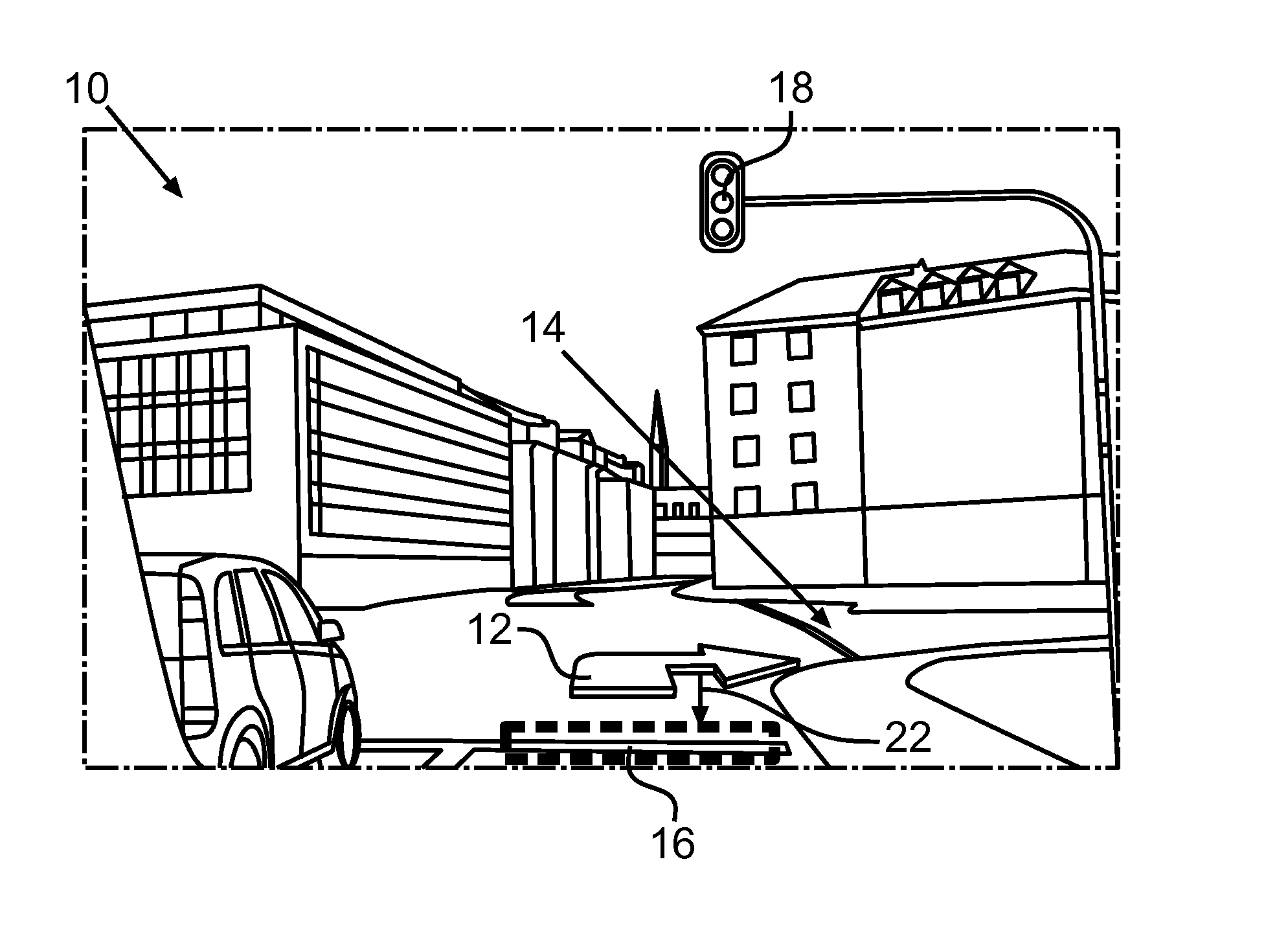
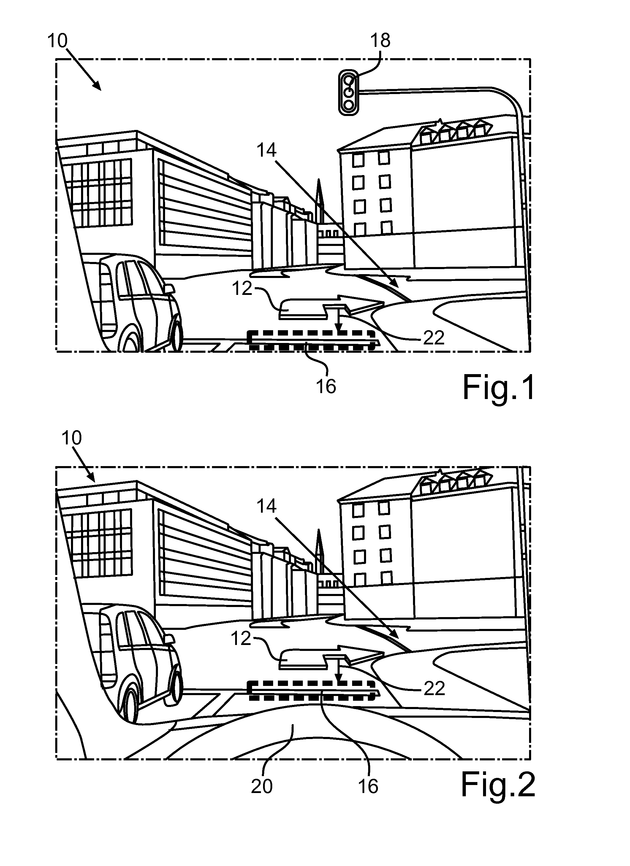
[0027]FIG. 1 shows a vehicle environment 10, as it looks through a vehicle windshield in the field of vision of a driver (not shown) of the vehicle. As an example of an artificially generated image information item, a turn arrow 12 is inserted in the vehicle environment 10. This happens because an image generator of a head-up display projects the turn arrow 12 onto the windshield of the vehicle. The turn arrow indicates that one should turn at an intersection 14, and it is shown as an example of an image information item that facilitates the navigation of the vehicle. Such image information items projected into the vehicle environment 10 by means of, e.g., insertion in the driver's field of vision are also known as augmented reality.

[0028]It is possible that due to braking the vehicle may execute a pitching motion, in other words a rotary motion about its transverse axis. If the turn arrow 12 in such a case were to remain in the same position as in the view frame of the projection s...


PUM


Abstract

A method for operating a camera assembly for a vehicle involves displaying at least one image information item on a surface. In response to a proper motion of the surface, the at least one image information item is changed in such a way that the proper motion of the surface is at least largely compensated for. To this end, at least two sequential images are captured by a camera of the camera assembly. At least one reference object that is present in both sequential images is identified. The at least one image information item is fixed in relation to the at least one reference object during the proper motion of the surface.

Description

CROSS-REFERENCE TO RELATED APPLICATIONS[0001]The present application is related to PCT International Application PCT / EP2012 / 005131, filed Dec. 12, 2012, a U.S. national stage of which is U.S. ______ (Attorney Docket No. 095309.66827US).BACKGROUND AND SUMMARY OF THE INVENTION[0002]Exemplary embodiments of the present invention relate to a method for operating a camera assembly for a vehicle, in which at least one image information item is displayed on a surface. In response to a proper motion of the surface, the at least one information item is changed in such a way that the proper motion of the surface is at least largely compensated for. Exemplary embodiments of the present invention further relate to a camera assembly.[0003]German patent document DE 10 2009 045 169 A1 describes a display device for a vehicle with an image generator for generating an image, and with imaging optics for projecting the image onto a windshield of the vehicle. A camera detects a head position or viewing...

Claims


Application Information

Patent Timeline
Patent Type & Authority Applications(United States)
IPC IPC(8): G06T19/00H04N5/74G06T3/60H04N7/18
CPCG06T19/006H04N7/183H04N5/74G06T2215/16G06T2207/20004G06T2207/30268G06T3/60G01C21/365G02B27/01G01C21/3602G01C21/3647G02B2027/014B60K35/00B60K2370/176B60K2370/166
Inventor MAIHOEFER, CHRISTIAN
Owner DAIMLER AG
Why Eureka
Try Eureka