Cooling system of nuclear reactor containment structure

a technology of containment structure and cooling system, which is applied in the direction of nuclear engineering, nuclear elements, greenhouse gas reduction, etc., can solve the problems of deteriorating removal performance of fission products required for filters, damage to pipes and devices related thereto, and long time-consuming power restoration of filtered exhaust apparatuses

Active Publication Date: 2014-12-25
KOREA HYDRO & NUCLEAR POWER CO LTD
View PDF18 Cites 4 Cited by
  • Summary
  • Abstract
  • Description
  • Claims
  • Application Information

AI Technical Summary

Benefits of technology

[0011]Additional advantages and features of the invention will be set forth in part in the description which follows and in part will become apparent to those having ordinary skill in the art upon examination of the following or may be learned from practice of the invention.

Problems solved by technology

However, it is identified that power restoration of the filtered exhaust apparatus may take a long time after the Fukushima nuclear accident.
In addition, when the filtered exhaust apparatus is driven for a long time, condensed water within an exhaust apparatus has an increasing temperature and a filter has an increasing temperature due to fission products accumulated in the filter, thereby rapidly deteriorating removal performance of fission products required for the filter.
Meanwhile, since the conventional systems for condensing and filtering vapor cause undesired water hammer by releasing vapor into an overcooled water tank in an initial operation of the filtered exhaust apparatus, pipes and devices related thereto may be damaged.

Method used


Image

  • Cooling system of nuclear reactor containment structure
  • Cooling system of nuclear reactor containment structure
  • Cooling system of nuclear reactor containment structure

Examples


first embodiment

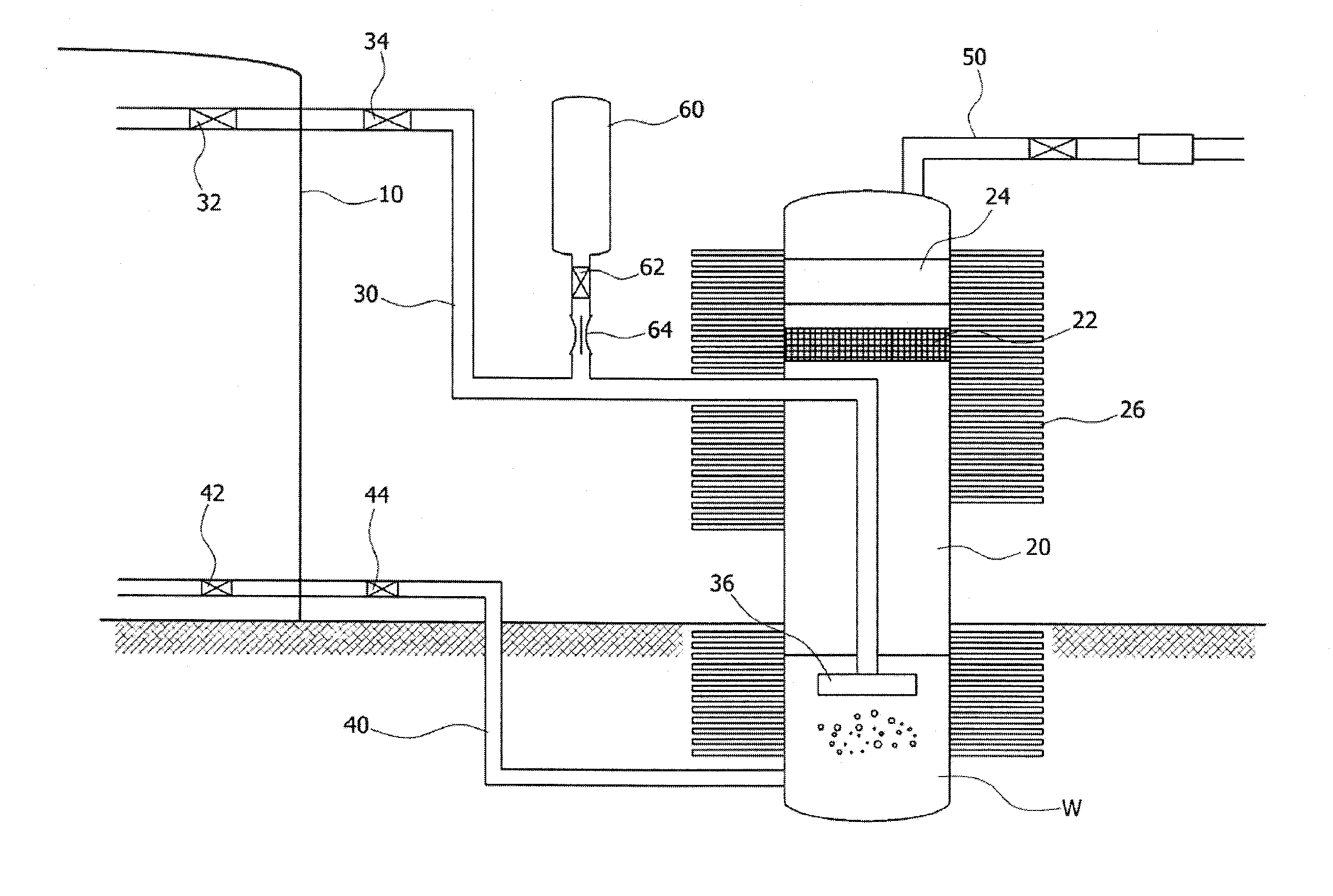
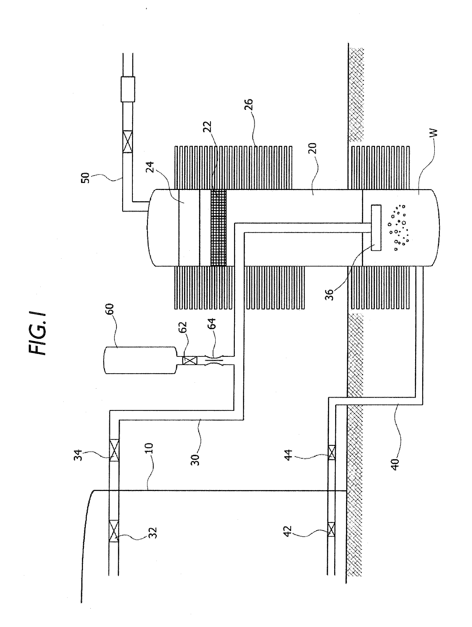
[0039]FIG. 1 is a diagram illustrating an overall structure of a cooling system of a nuclear reactor containment structure according to the present invention.

[0040]As shown in FIG. 1, the cooling system of a nuclear reactor containment structure according to the first embodiment of the present invention includes a containment structure 10, a pressure vessel or water tank 20, a release pipe 30, and a recovery pipe 40.

[0041]The containment structure 10 is a structure housing a nuclear reactor and is formed in the form of a typical building to include various related facilities therein.

[0042]The pressure vessel 20 receives condensed water W therein and has a receiving space located such that at least a portion of the pressure vessel is lower than a bottom of the containment structure 10. In the present embodiment, the pressure vessel 20 is buried under the ground at a lower portion thereof, and thus the buried portion is located lower than the bottom of the containment structure 10.

[00...

second embodiment

[0061]FIG. 4 is a diagram illustrating an overall structure of a cooling system of a nuclear reactor containment structure according to the present invention.

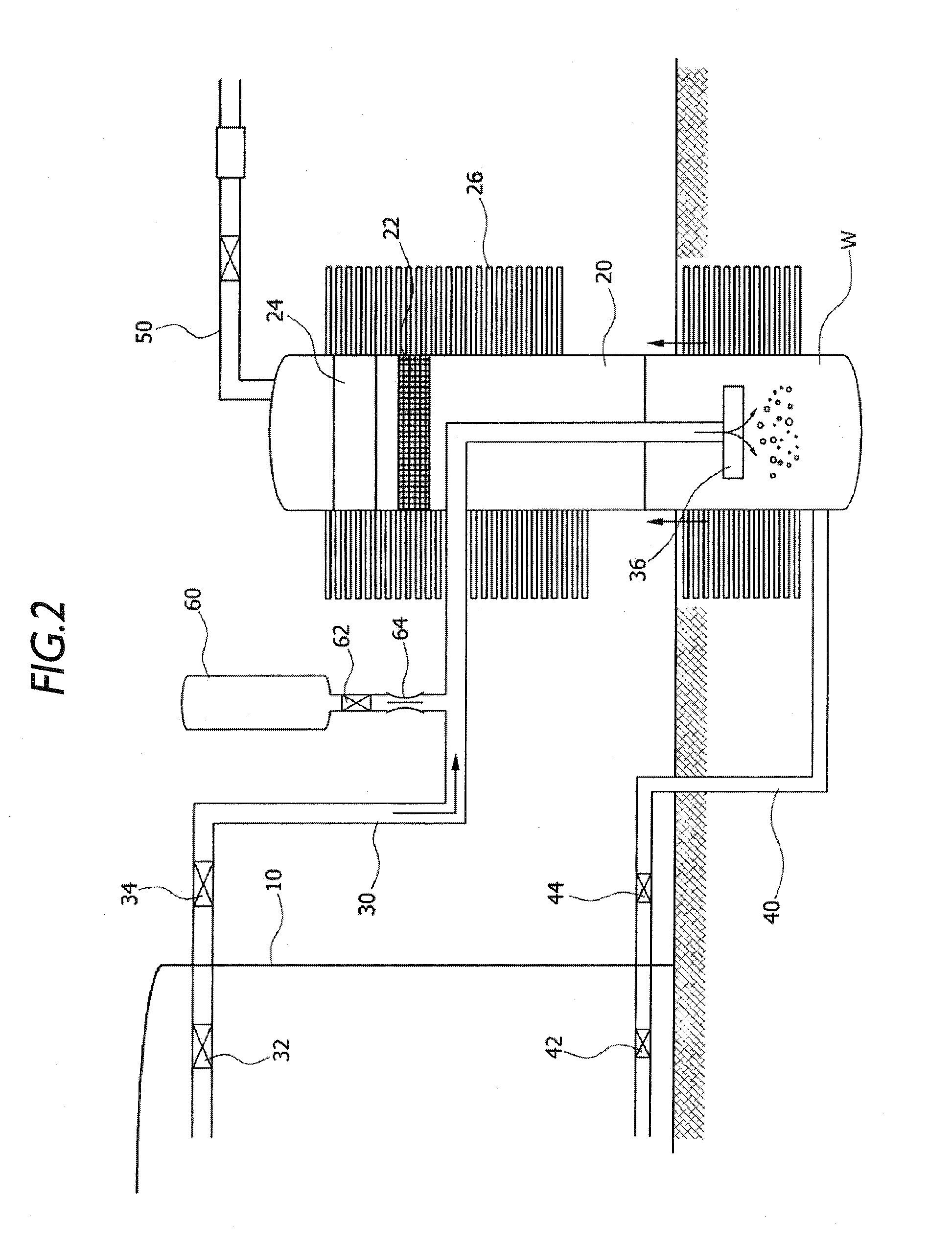
[0062]As shown in FIG. 4, the cooling system of a nuclear reactor containment structure according to the second embodiment of the present invention has configurations similar to those of the above-mentioned first embodiment, but differs in that a cooling pool receiving cooling water S is formed around the lower portion of the pressure vessel 20. In the present embodiment, the cooling pool has a predetermined depth defined under the ground surface so that a lower portion of the pressure vessel 20 is exposed to the cooling water S. Thus, the cooling pool may reduce an increase in temperature within the pressure vessel 20, together with the radiation fins 26.

third embodiment

[0063]FIG. 5 is a diagram illustrating an overall structure of a cooling system of a nuclear reactor containment structure according to the present invention.

[0064]As shown in FIG. 5, the cooling system of a nuclear reactor containment structure according to the third embodiment of the present invention has configurations similar to those of the above-mentioned first embodiment, but differs in that the cooling system further includes a supply tank connected to the pressure vessel 20 by a supply pipe 70 to supply the receiving space with condensing water. Since the provision of the supply tank allows the condensed water W in the pressure vessel 20 having an increased temperature equal to or greater than a certain degree to be supplied with new condensing water, the temperature in the pressure vessel may be decreased.

[0065]The supply tank may include a temperature sensor for sensing a temperature in the receiving space, and the supply pipe 70 may be provided with a supply valve 72 whi...


PUM


Abstract

A nuclear power plant includes a nuclear reactor containment structure housing a nuclear reactor, a pressure vessel containing condensed water therein and having a receiving space located lower than a bottom of the containment structure, a release pipe connecting the containment structure to the pressure vessel such that water vapor and fission products generated in the containment structure in the event of an accident is capable of flowing into the pressure vessel, and a recovery pipe connecting the pressure vessel to the containment structure such that the condensed water received in the pressure vessel is capable of flowing into the containment structure. When a level of the condensed water received in the pressure vessel is higher than a water level in the containment structure, the condensed water flows from the pressure vessel toward the containment structure by a water head difference.

Description

CROSS-REFERENCE TO RELATED APPLICATION[0001]This application claims priority to and the benefit of Korean Patent Application No. 10-2013-0070458, filed on Jun. 19, 2013 and Korean Patent Application No. 10-2014-0035994, filed on Mar. 27, 2014, the disclosure of which is incorporated herein by reference in its entirety.BACKGROUND[0002]1. Field[0003]The present disclosure relates to a cooling system for cooling a nuclear reactor containment structure in the event of a severe accident, and more particularly, to a cooling system of a nuclear reactor containment structure, capable of being driven for a long time by natural convection without supply of power.[0004]2. Discussion of Related Art[0005]In order to prevent damage of a containment building housing a nuclear reactor due to an increase in pressure of the containment building and a large leakage of fission products due to the damage when a severe accident occurs in the nuclear reactor, the containment building includes a release po...

Claims


Application Information

Patent Timeline
Patent Type & Authority Applications(United States)
IPC IPC(8): G21C15/18
CPCG21C15/18G21C9/004G21C13/022Y02E30/30
Inventor SONG, JIN HOHA, KWANG SOONKIM, HWAN YEOLSONG, YONG MANN
Owner KOREA HYDRO & NUCLEAR POWER CO LTD
Why Eureka
Try Eureka