Cable-type secondary battery

Active Publication Date: 2014-12-25
LG ENERGY SOLUTION LTD
10 Cites 3 Cited by

AI-Extracted Technical Summary

Problems solved by technology

Because a predetermined mounting space for the electrode assembly is necessary in this process, the cylindrical, prismatic or pouch shape of the secondary batteries is a limitation in developing various shapes of mobile devices.
However, such battery has poor flexibility.
The linear batteries use a polymer electrolyte to form an electrolyte layer, but this causes difficulties in the inflow of the electrolyte into an electrode active material, thereby increasing the resistance of the batteries and deteriorating the capacity and cycle characteristics thereof.
Also, the cable-type batteries may have spaces that are ununiformly...

Method used

[0106]Meanwhile, if a wire-form current collector is used in batteries, since a value of line resistance is generally higher than that of sheet resistance, the wire-form current collector may exhibit high resistance as compared with a sheet-form current collector, thereby deteriorating battery performances. However, the present invention uses a sheet-form current collector as an inner current collector and an outer current collector, thereby decreasing the resistance of the battery and eventually improving battery performances.
[0108]In addition, a cable-type secondary battery according to another embodiment of the present disclosure includes an inner electrode supporter; a sheet-form inner electrode spirally wound on the outer surface of the inner electrode supporter; and a sheet-form laminate of separation layer-outer electrode, spirally wound on the outer surface of the inner electrode, wherein the laminate of separation layer-outer electrode is formed by carrying out compression for the integration of a separation layer for preventing a short circuit, and an outer electrode.
[0109]In addition, a cable-type secondary battery according to another embodiment of the present disclosure includes an inner electrode supporter; a sheet-form laminate of inner electrode-separation layer, spirally wound on the outer surface of the inner electrode supporter; and a sheet-form outer electrode wound on the outer surface of the laminate of inner electrode-separation layer, wherein the laminate of inner electrode-separation layer is formed by carrying out compression for the integration of an inner electrode and a separation layer for preventing a short circuit. Here, the term ‘spirally’ used herein refers to represent a helix shape that turns around at a certain area while moving, including general spring forms.
[0110]In addition, the sheet-form laminate of inner electrode-separation layer-outer electrode, the sheet-form laminate of separation layer-outer electrode, and the sheet-form laminate of inner electrode-separation layer may be spirally wound so that it is not overlapped in its width. At this time, each sheet-form laminate may be spirally wound with space within the double length of its width so that it is not overlapped, in order to prevent the performance of the battery from deteriorating.
[0111]In addition, the sheet-form laminate of inner electrode-separation layer-outer electrode, the sheet-form laminate of separation layer-outer electrode, and the sheet-form laminate of inner electrode-separation layer may be spirally wound so that it is overlapped in its width. At this time, each sheet-form laminate may be spirally wound so that the width of its overlapped part is within 0.9 folds of the width of the each sheet-form laminate, in order to suppress excessive increase of an internal resistance of the battery.
[0115]When the electrode active material layer comprises a binder and the separation layer is a separator comprising the binder and inorganic mixture, the binder of the electrode active material layer or the binder release from the separator may provide stronger adhesiveness in an interface between the separation layer and the electrodes.
[0116]In the present disclosure, the laminate 10 of inner electrode-separation layer-outer electrode may be formed by maintaining a peel strength of 15 to 300 N/m between the inner electrode 7 and the separation layer 13 or between the separation layer 13 and the outer electrode 5 during compression for the integration thereof, the laminate 20 of separation layer-outer electrode may be formed by maintaining a peel strength of 15 to 300 N/m between the separation layer 23 and the outer electrode 5 during compression for the integration thereof, and the laminate 30 of inner electrode-separation layer may be formed by maintaining a peel strength of 15 to 300 N/m between the inner electrode 7 and the separation layer 33 during compression for the integration thereof. When each peel strength satisfies such a range, an adequate adhesiveness between the separation layer and the electrodes can be obtained without separation thereof, thereby achieving good integration of the separation layer and the electrodes.
[0119]In contrast, the present invention uses the laminate of a separation layer and an electrode being integrated by pre-adhesion. That is, such a laminate of separation layer-electrode layer can be used in a cable-type battery to prevent an internal short circuit due to the contact of an inner electrode and an outer electrode because the separation layer and the electrode can integrally move even though the cable-type battery is bent. As a result, the flexibility of the battery can be enhanced and the separation layer is minimized from overlapping in both boundaries thereof, thereby providing good ionic conductivity and contributing to the improvement of battery performances.
[0125]In the present disclosure, the open-structured inner electrode supporter may be in the form of a hollow fiber, a wound wire, a wound sheet or a mesh, and also the supporter may have pores on the surface thereof, allowing the free movement of an electrolyte solution into the inner electrode active material layer and the outer electrode active material layer to provide good wetting.
[0126]The open-structured inner electrode supporter can maintain the linear shape of the cable-type secondary battery and can prevent the disruption or deformation of the electrode structure, thereby ensuring the flexibility of the cable-type secondary battery.
[0135]Meanwhile, when cable-type secondary batteries are subject to external forces by bending or twisting, an electrode active material layer may be released from a current collector. For this reason, large amounts of binder components are used in the e...

Benefits of technology

[0069]Thus, in the cable-type secondary battery of the present disclosure, since the electrodes and the separation layer are adhered to each other and integrated, the separation layer coming into contact with the electrodes absorbs an electrolyte solution to induce the uniform supply of the electrolyte solution into the outer electrode active material layer, thereby enhancing the stability and performances of the cable-type secondary battery.
[0070]In addition, the cable-type secondary battery of the present disclosure uses a sheet-form electrode with excluding a wire-form current collector having high resistance, thereby decreasing the resistance of the battery and eventually improving battery performances.
[0071]In ...

Abstract

The present disclosure provides a cable-type secondary battery, comprising: an inner electrode supporter; and a sheet-form laminate of inner electrode-separation layer-outer electrode, spirally wound on the outer surface of the inner electrode supporter, wherein the laminate of inner electrode-separation layer-outer electrode is formed by carrying out compression for the integration of an inner electrode, a separation layer for preventing a short circuit, and an outer electrode. In the cable-type secondary battery of the present disclosure, since the electrodes and the separation layer are adhered to each other and integrated, the separation layer coming into contact with the electrodes absorbs an electrolyte solution to induce the uniform supply of the electrolyte solution into the outer electrode active material layer, thereby enhancing the stability and performances of the cable-type secondary battery.

Application Domain

Technology Topic

Image

  • Cable-type secondary battery
  • Cable-type secondary battery
  • Cable-type secondary battery

Examples

  • Experimental program(2)

Example

EXAMPLE
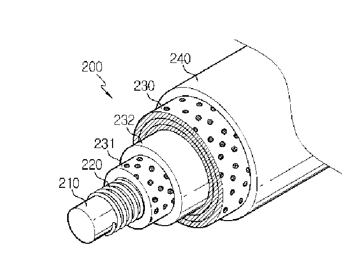
[0194]Four Cu-wires having a diameter of 250 μm were wound with crossing with each other to obtain an open-structured inner electrode supporter in which a hollow core for supplying lithium ions in the form of a spring can be present.
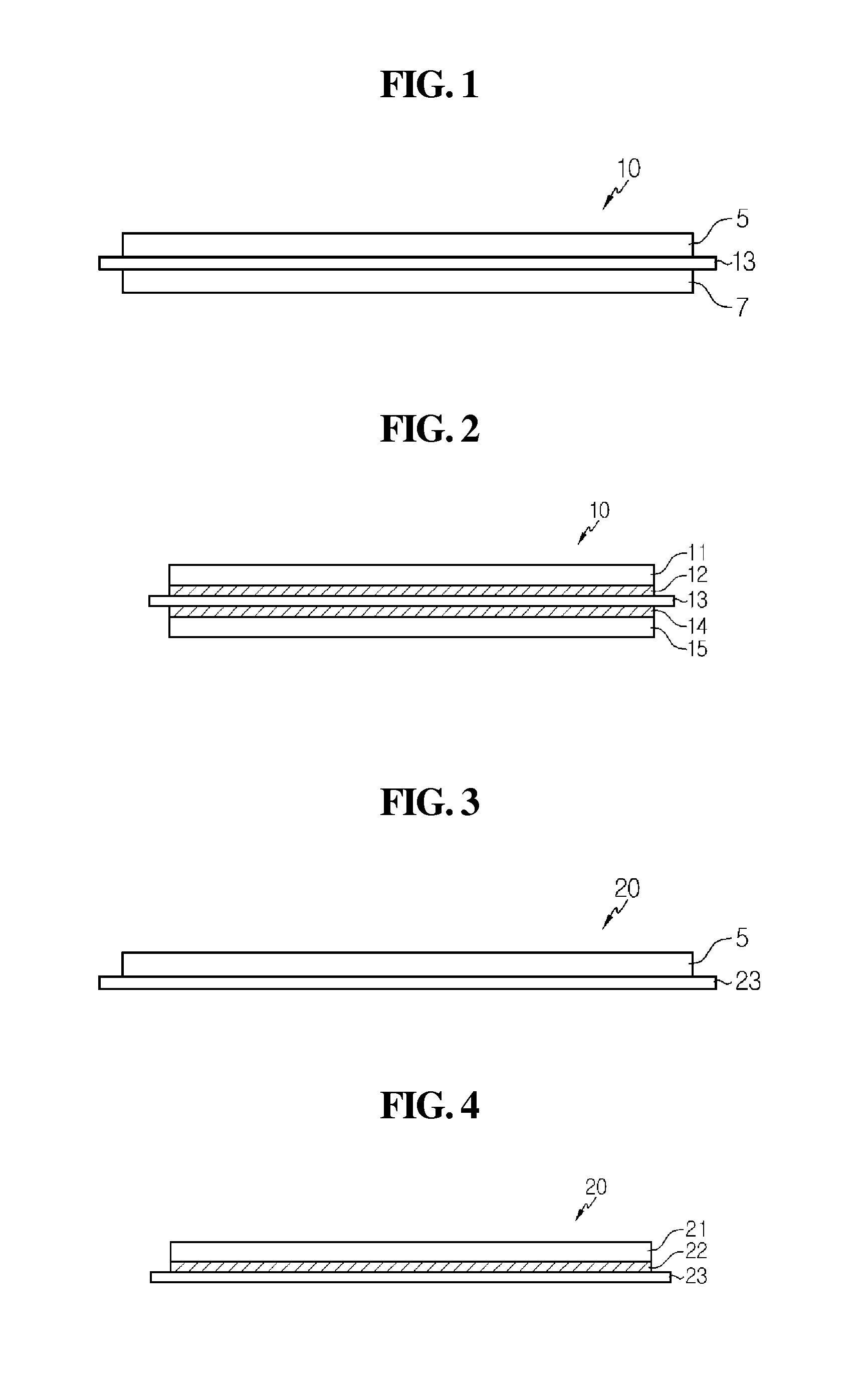
[0195]Then, 70 wt % of graphite as an anode active material, 5 wt % of Denka black as a conductive material and 25 wt % of PVdF as a binder were mixed to obtain an anode active material-containing slurry. The slurry was coated on a Cu-foil and slit into a piece with a width of 2 mm, to obtain a sheet-form inner electrode (anode).
[0196]Meanwhile, 80 wt % of LiCoO2 as a cathode active material, 5 wt % of Denka black as a conductive material and 15 wt % of PVdF were mixed to obtain a cathode active material-containing slurry. The slurry was coated on an Al-foil and slit into a piece with a width of 2 mm, to obtain a sheet-form outer electrode (cathode).
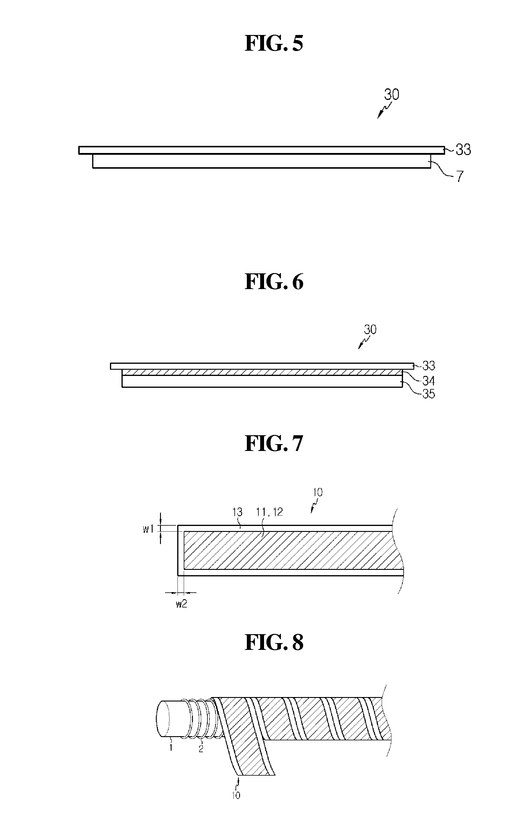
[0197]Next, the sheet-form inner electrode was adhered with a sheet-form separator consisting of a porous substrate obtained from inorganic particles and a binder polymer, followed by lamination by using a roll press, to obtain a sheet-form laminate of the inner electrode and the separator being integrated by adhesion.
[0198]The laminate of the inner electrode and the separator thus obtained was wound on the outer surface of the open-structured inner electrode supporter.
[0199]Subsequently, the sheet-form outer electrode was wound on the outer surface of the wound laminate of the inner electrode and the separator. Then, on the outer surface of the wound outer electrode, a heat-shrinkable tube having a moisture-blocking layer was applied and contracted with heat, to form a protection coating layer.
[0200]Then, a non-aqueous electrolyte solution (1M LiPF6, EC:PC=1:1 (volume ratio)) was introduced in the center of the inner electrode using a syringe, to form a core for supplying lithium ions, followed by completely sealing. Thereby, a cable-type secondary battery was prepared.
Comparative Example

Example

[0201]The procedures of Example 1 were repeated except that the sheet-form inner electrode was wound on the outer surface of the inner electrode supporter and the separator was wound on the outer surface of the wound sheet-form inner electrode, instead of the step of wining the laminate of the inner electrode and the separator on the outer surface of the open-structured inner electrode supporter, to prepare a cable-type secondary battery.
Evaluation of Battery Performances
[0202]For the cable-type secondary batteries prepared in the Example and the Comparative Example, 100 cycles of charge/discharge processes were carried out with a current density of 0.3 C at a voltage condition of 4.2 to 3.0 V, so as to confirm life characteristics and a voltage profile to normal capacity.
[0203]FIGS. 13 and 14 are each a graph showing a voltage profile to normal capacity during charging and discharging of cable-type secondary batteries prepared in the Example and the Comparative Example of the present disclosure. From these, it was confirmed that the cable-type secondary battery of the Example exhibited resistance decrease as compared with the Comparative Example.
[0204]Also, FIG. 15 is a graph showing the cycle life characteristics of cable-type secondary batteries prepared in the Example and the Comparative Example of the present disclosure. From this, it was confirmed that the cable-type secondary battery of the Example exhibited an increase in rate retention ratio, i.e., superior life characteristics, as compared with the Comparative Example.
[0205]According to the results above, a laminate of a separation layer and an electrode is applied in cable-type secondary batteries to minimize spaces between the electrode and the separation layer through integration, thereby improving the impregnation of an electrolyte solution into the micropores of the separation layer. From this, the resistance of the cable-type secondary batteries can decrease and the life characteristics thereof can be improved.
APPLICABILITY TO THE INDUSTRY
[0206]The present disclosure has been described in detail. However, it should be understood that the detailed description and specific examples, while indicating preferred embodiments of the disclosure, are given by way of illustration only, since various changes and modifications within the spirit and scope of the disclosure will become apparent to those skilled in the art from this detailed description.

PUM

no PUM

Description & Claims & Application Information

We can also present the details of the Description, Claims and Application information to help users get a comprehensive understanding of the technical details of the patent, such as background art, summary of invention, brief description of drawings, description of embodiments, and other original content. On the other hand, users can also determine the specific scope of protection of the technology through the list of claims; as well as understand the changes in the life cycle of the technology with the presentation of the patent timeline. Login to view more.

Similar technology patents

Array substrate of display panel

ActiveUS20160056182A1Decrease resistanceImprove electrical characteristic and reliabilitySolid-state devicesNon-linear opticsEngineeringSemiconductor
Owner:INNOLUX CORP

Method for processing an electroplated copper film in copper interconnect process

ActiveUS20160247717A1Decrease resistanceImprove contact resistanceSolid-state devicesSemiconductor/solid-state device manufacturingElectroplatingContact resistance
Owner:SHANGHAI INTEGRATED CIRCUIT RES & DEV CENT

Resistive carbon composite material

InactiveUS20170171917A1Increase conductivityDecrease resistanceMaterial nanotechnologyHeating element materialsCarbon blackAdhesive
Owner:OBSHHESTVO S OGRANICHENNOJ OTVETSTVENNOSTJU INZHINIRIINGOVAJA KOMPANIJA TEPLOFON

Classification and recommendation of technical efficacy words

  • Decrease resistance
  • Improve performance

Enhanced permanent magnet electromagnetic actuator for an electronic valve actuation system of an engine

InactiveUS20050279300A1Decrease resistanceDecrease transition timeMachines/enginesNon-mechanical valveInternal combustion engineVALVE PORT
Owner:FORD GLOBAL TECH LLC
Why Eureka
Try Eureka