Reverse cage intervertebral fusion implants

a technology of intervertebral fusion and cage, which is applied in the field of devices and implants, can solve the problems of chronic back pain, spinal disc or vertebral body displacement, etc., and achieve the effects of promoting bone and fusion growth, improving and safer methods of spinal fusion, and restoring or substantially restoring the natural shape and curvatur

Inactive Publication Date: 2014-12-25
INST FOR MUSCULOSKELETAL SCI & EDUCATION
View PDF10 Cites 24 Cited by
  • Summary
  • Abstract
  • Description
  • Claims
  • Application Information

AI Technical Summary

Benefits of technology

[0013]Low-profile, reverse cage intervertebral fusion implants for spinal fusion, especially in the lumbar spine, kits containing the implants, including suitable stabilization means, and methods of using the implants and kits are described herein. The implants have a spacer anteriorly located and an endplate posteriorly located. The reverse cage implants are placed, typically via an anterior approach, although other approaches can also be employed, within the intervertebral space between adjacent superior and inferior vertebra. The implants can restore or substantially restore the natural shape and curvature locally of the vertebral region while promoting growth of bone and fusion of adjacent vertebral bodies.

Problems solved by technology

The spinal disc and / or vertebral bodies can be displaced or damaged due to trauma, disease, degenerative defects, or wear over an extended period of time.
One result of this displacement or damage to a spinal disc or vertebral body can be chronic back pain.
Common causes of failure in spinal fusion include slippage of the implant, breakage of the plates, or the backing out of screws that secure the implant and / or bone fixation plate.
Screws back out, typically as a result of the failure of the screws to achieve a sufficient purchase in the bone; although the stripping of the threads on the screws also causes this problem.

Method used


Image

  • Reverse cage intervertebral fusion implants
  • Reverse cage intervertebral fusion implants
  • Reverse cage intervertebral fusion implants

Examples


Embodiment Construction

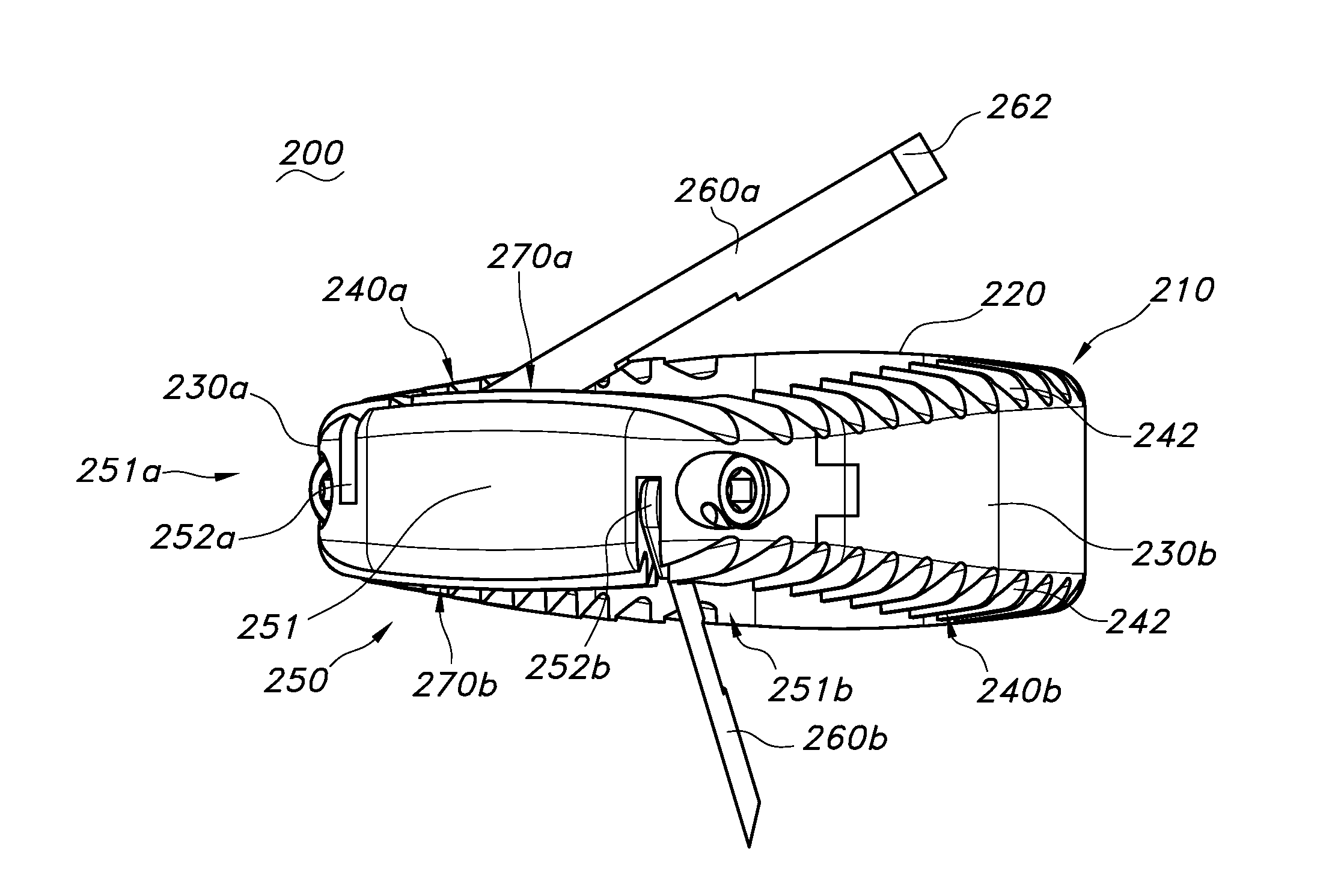
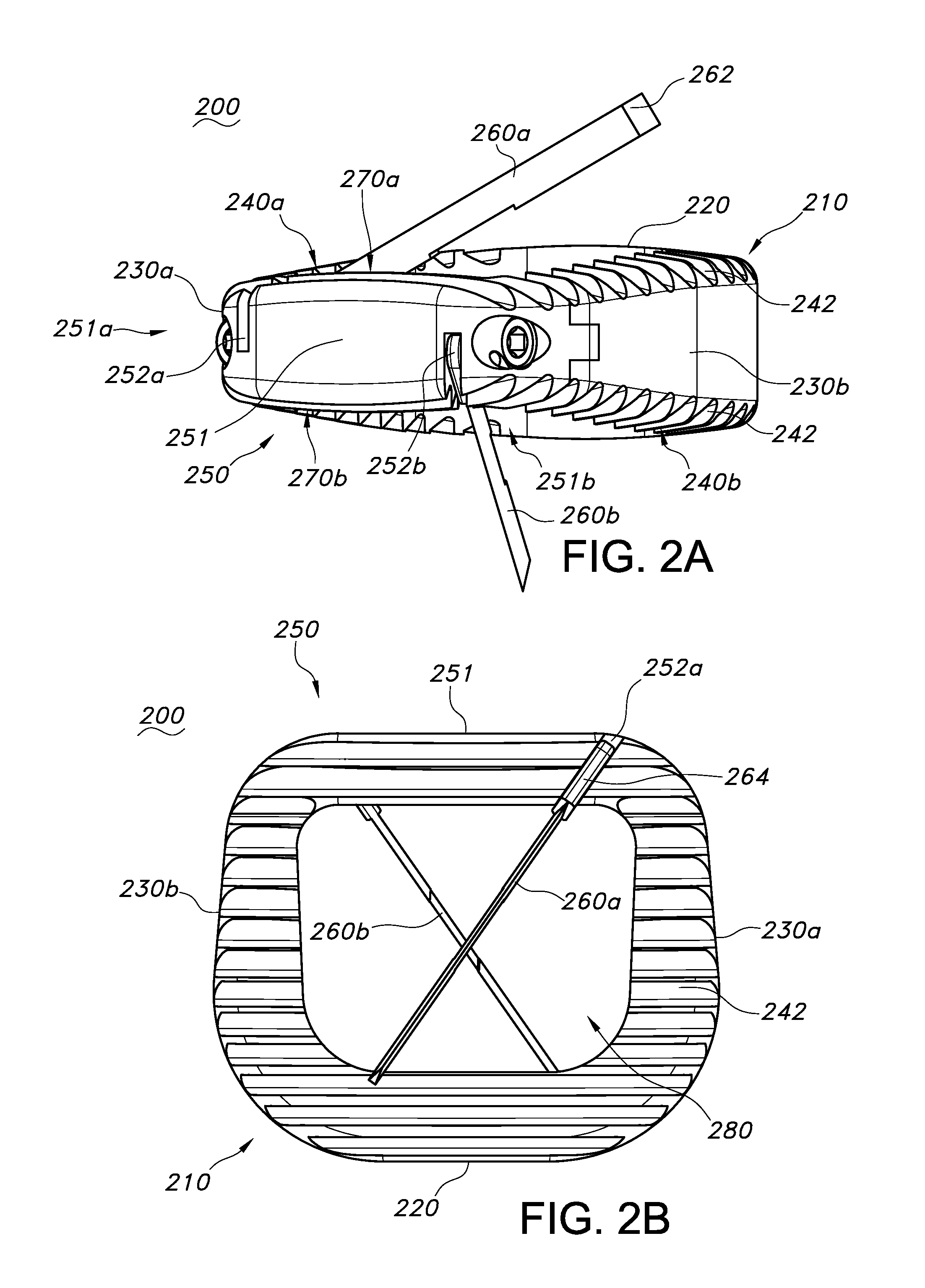
[0023]Low-profile reverse cage intervertebral fusion implants are disclosed herein. The reverse cage implants include a spacer region anteriorly located and an endplate posteriorly located. Reverse cage intervertebral implants are useful for spinal fusion, especially in the lumbar spine. The reverse cage implants are placed within the intervertebral space between adjacent superior and inferior vertebra. Typically an anterior approach is used for placement of the implant, however other approaches can also be employed. The implants restore or largely restore the natural shape and curvature locally of the vertebral region while promoting growth of bone and fusion of adjacent vertebral bodies.

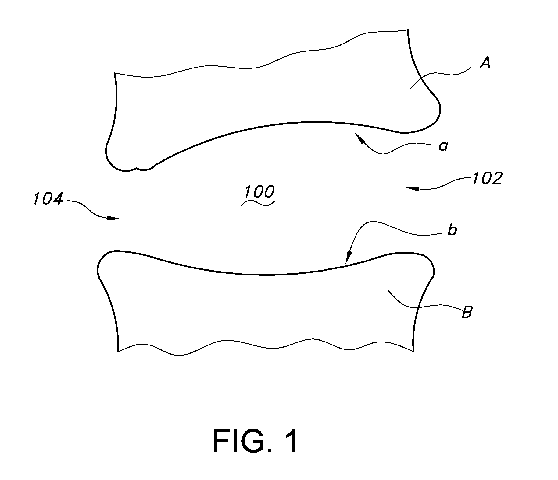
[0024]Some basic terms and measures used to characterize the regions and dimension of the intervertebral space are depicted in FIG. 1. FIG. 1 is a dexter projection into the sagittal plane of the body of the intervertebral space 100 between an idealized superior (upper) vertebra A and an idealized ...


PUM


Abstract

Low-profile reverse cage intervertebral implants are provided having an endplate positioned on the posterior side of the cage. Having the endplate positioned posteriorly provides several advantages including placement of fastening means away from blood vessels anterior to the intervertebral region as well as placement of bone screws to prevent backing out. The endplates are overall smaller than corresponding endplates for traditional (anterior) positioning. Implants are provided having various means for securing the implant in the intervertebral space, including one or more blades and / or one or more bone screws.

Description

CROSS-REFERENCE TO RELATED APPLICATIONS[0001]This application claims priority to U.S. Provisional Application Ser. No. 61 / 837,342, filed Jun. 20, 2013, the disclosure of which is incorporated herein by reference in its entirety.FIELD OF THE INVENTION[0002]The present disclosure is generally in the field of devices and implants for positioning and immobilizing two or more adjacent vertebra.BACKGROUND OF THE INVENTION[0003]The spinal disc and / or vertebral bodies can be displaced or damaged due to trauma, disease, degenerative defects, or wear over an extended period of time. One result of this displacement or damage to a spinal disc or vertebral body can be chronic back pain. Intervertebral disc degeneration impacts the majority of people, with more than 60% of patients beyond age 40 displaying some level of disc degeneration on an MRI. This is most prevalent in the lumbar spine.[0004]The standard treatment for chronic pain related to damaged or displaced discs is lumbar spinal fusion...

Claims


Application Information

Patent Timeline
Patent Type & Authority Applications(United States)
IPC IPC(8): A61F2/44
CPCA61F2002/30576A61F2/447A61B17/86A61F2/30749A61F2/4455A61F2002/30433A61F2002/30492A61F2002/30772A61F2002/30774A61F2002/30787A61F2002/30904
Inventor DUFFIELD, WILLIAMTORRETTI, JOEL
Owner INST FOR MUSCULOSKELETAL SCI & EDUCATION
Why Eureka
Try Eureka