Brake pad assembly

a technology of brake pads and assembly parts, which is applied in the direction of brake cooling, brake systems, friction linings, etc., can solve the problems of slowing down the vehicle, speed of rotation of the rotor, and speed of the wheel rotation,

Inactive Publication Date: 2015-01-01
MENNIE TREVOR MICHAEL
View PDF4 Cites 26 Cited by
  • Summary
  • Abstract
  • Description
  • Claims
  • Application Information

AI Technical Summary

Benefits of technology

[0082]The peripheral wall may be attached to, or form part of, a translating portion of the brake pad structure (i.e. a portion of the brake pad structure which moves away and towards the brake rotor under braking and non braking), such as the support structure of the brake pad. In these embodiments, the peripheral wall may span the gap between the brake pad and the brake rotor so as to prevent brake dust from the braking surface of the brake pad from entering the surrounding atmosphere (only) under braking conditions.
[0083]Alternatively, the peripheral wall may be attached to, or form part of, the brake rotor or a non-translating portion of the brake pad structure (i.e. a portion of the brake pad structure which does not move away and towards the brake rotor u

Problems solved by technology

When the brake is activated, the brake pad is pressed firmly against the brake rotor, and friction between the static brake pad and rotating rotor causes the speed of rotation of the rotor, and therefore the speed of rotation of the wheel, to slow.
This in turn slows the vehicle.
However, a problem with these arrangements exists in that intermittent or constant contact between the brake pad and brake rotor w

Method used


Image

  • Brake pad assembly
  • Brake pad assembly
  • Brake pad assembly

Examples


Embodiment Construction

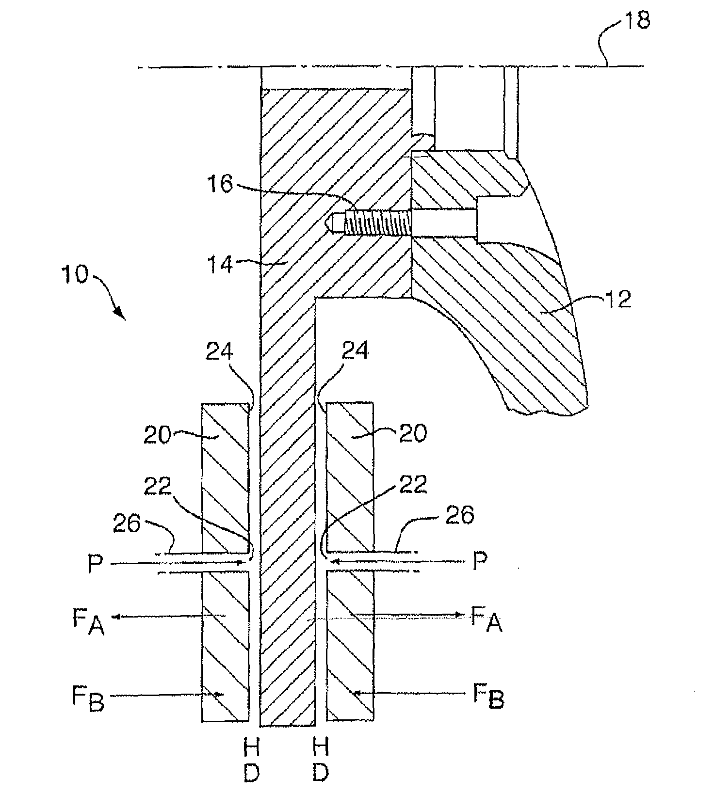
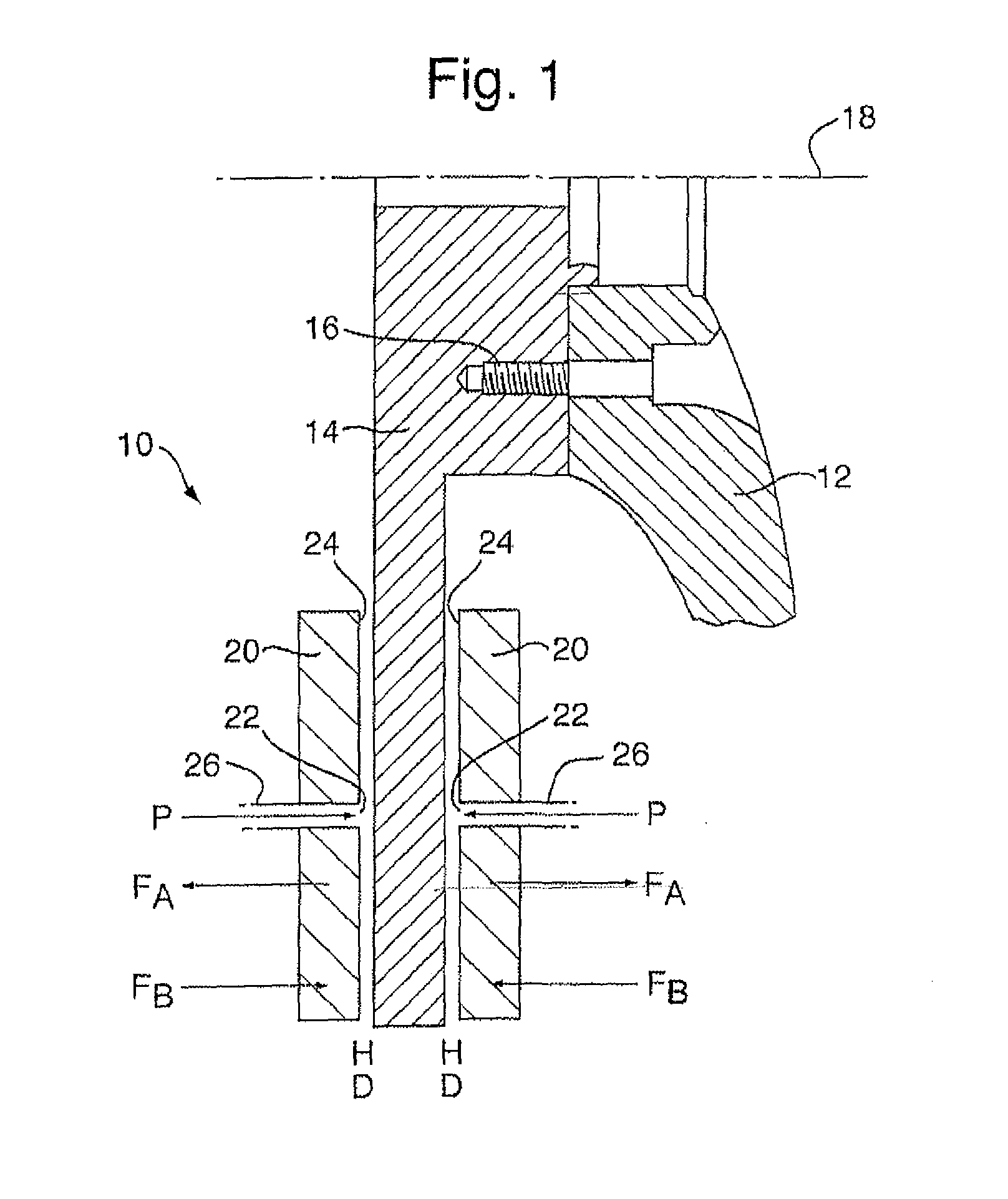
[0163]FIG. 1 is a cross sectional view of one embodiment of a brake system 10 for a motor vehicle. The brake system comprises a wheel hub 12 (shown in part) and a brake rotor 14 (brake disc) rotationally fixed to the wheel hub 12 by a fixing 16 such as a bolt. The wheel hub 12 and brake rotor 14 rotate about a centerline 18 when the vehicle is moving.

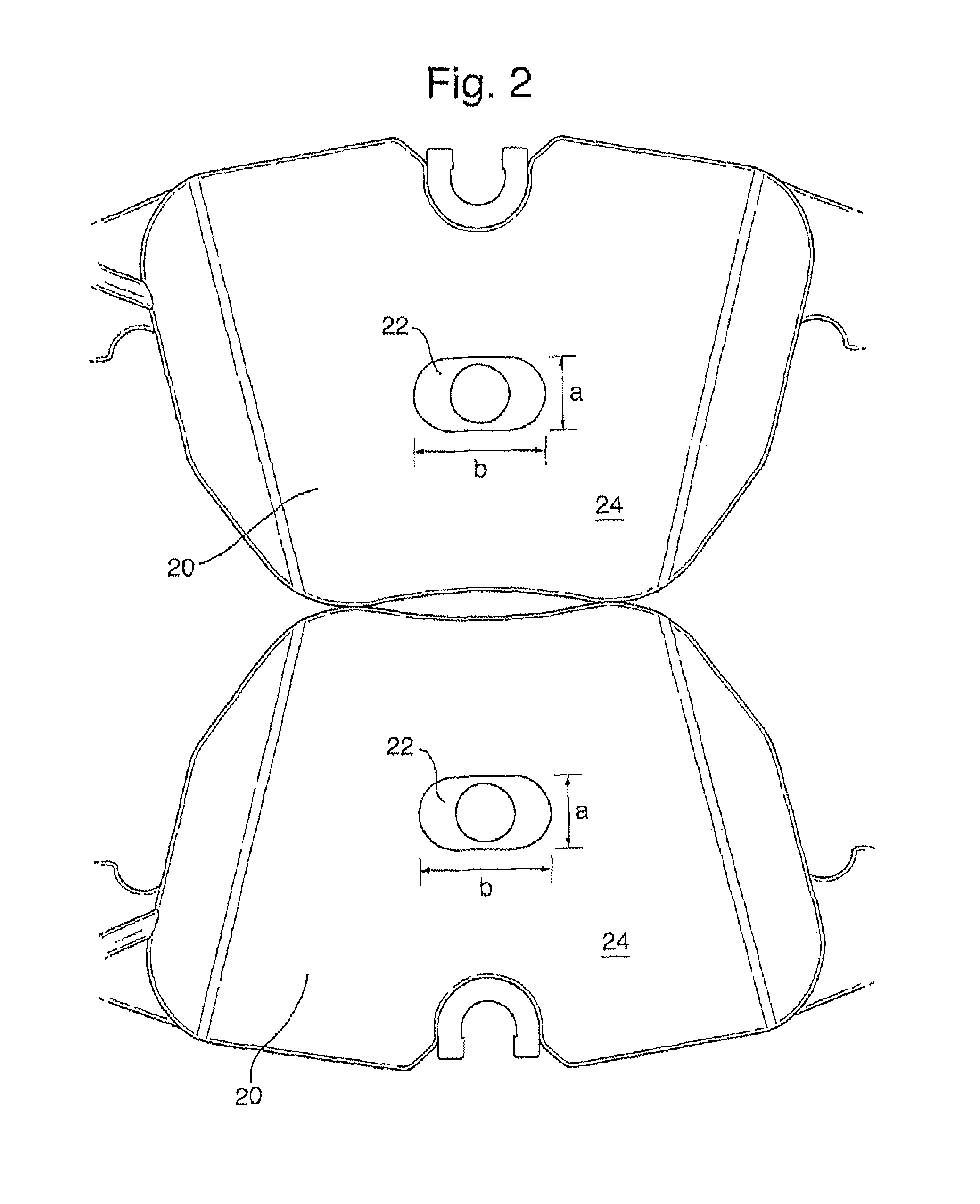
[0164]The brake system 10 further comprises a pair of brake pads 20 adjacent to the brake rotor 14. The brake pads 20 each comprise a friction material on a support structure (not shown). The brake pads 20 each have a braking surface 24 of the friction material that faces the brake rotor 14.

[0165]The brake pads are joined to one another by brake calipers (not shown), and the brake calipers are fixed to a static (non-rotating) part of the vehicle. The braking surfaces 24 (and therefore the friction material) of the brake pads 20 can be forced into firm contact with the brake rotor 14 using the brake calipers. The brake calipers are contr...


PUM


Abstract

A brake pad assembly includes a brake pad having a braking surface. A peripheral wall is provided about the periphery of the braking surface of the brake pad. A perimeter void is provided between the peripheral wall and at least a portion of the brake pad. The perimeter void is in fluid communication with the braking surface of the brake pad. A first set of one or more openings are provide in fluid communication with the perimeter void for removing brake dust from the braking surface of the brake pad.

Description

[0001]This application is entitled to the benefit of, and incorporates by reference essential subject matter disclosed in PCT Application No. PCT / IB2012 / 057040 filed on Dec. 6, 2012, which claims priority to Great Britain Application No. 1120957.4 filed Dec. 6, 2011, PCT Application No. PCT / GB2012 / 050473 filed Mar. 2, 2012, Great Britain Application No. 1204669.4 filed Mar. 16, 2012 and Great Britain Application No. 1217286.2 filed Sep. 27, 2012.BACKGROUND OF THE INVENTION[0002]1. Technical Field[0003]The present invention relates to a brake pad assembly, a brake system, a method of using a brake pad assembly or brake system, and a control system for a brake system. The present invention also relates to a kit and method for modifying a brake pad or brake system. Preferred embodiments of the present invention are directed to brake pads, brake pad assemblies or brake systems for vehicles.[0004]2. Background Information[0005]Brake systems for vehicles typically comprise a brake rotor f...

Claims


Application Information

Patent Timeline
IPC IPC(8): F16D65/00F16D65/092
CPCF16D65/0031F16D65/092B60T5/00F16D65/847F16D2065/783F16D2065/787F16D2069/004F16D2127/02B60T17/02F16D65/04F16D66/00F16D66/028
Inventor MENNIE, TREVOR MICHAEL
Owner MENNIE TREVOR MICHAEL
Why Eureka
Try Eureka