
Monitoring of liquid ejection system

a liquid ejection system and monitoring technology, applied in the direction of liquid transferring devices, instruments, transportation and packaging, etc., can solve the problems of affecting the quality of finished products being manufactured or processed, excessive waste of time, cleaning fluid, energy, etc., and achieve the effect of accurate reset of the arrangemen

Inactive Publication Date: 2015-01-01
ALFA LAVAL CORP AB
View PDF6 Cites 2 Cited by
  • Summary
  • Abstract
  • Description
  • Claims
  • Application Information

AI Technical Summary

Benefits of technology

The patent text describes a processing unit that can register and store the initial properties of a signal when a fluid nozzle ejects liquid towards the interior surface of a system. This allows for accurate reference properties to be obtained. Additionally, the processing unit can register and store the properties of the signal during a further measuring period to achieve a very accurate reset of the arrangement. The technical effect is that the processing unit provides a reliable and accurate way to measure and control the properties of a fluid nozzle during a cleaning or mixing process.

Problems solved by technology

Unwanted contaminants in the tank may negatively impact the quality of the finished product being manufactured or processed.
Alternatively, a cleaning duration may be prolonged, which however may lead to excessive waste of time, cleaning fluid, and energy.
Even though present techniques in some cases successfully ensure that cleaning of the interior of tanks or mixing of a content of a tank is accomplished, there may be problems in some cases, for example because of the size and shape of the tank, the type of substance to be cleaned of from the tank interior or mixed in the tank, varying climate conditions in the environment surrounding the tank, irregular or deficient behavior of components cooperating with the liquid ejection apparatus etc.

Method used


Image

  • Monitoring of liquid ejection system
  • Monitoring of liquid ejection system
  • Monitoring of liquid ejection system

Examples


Embodiment Construction

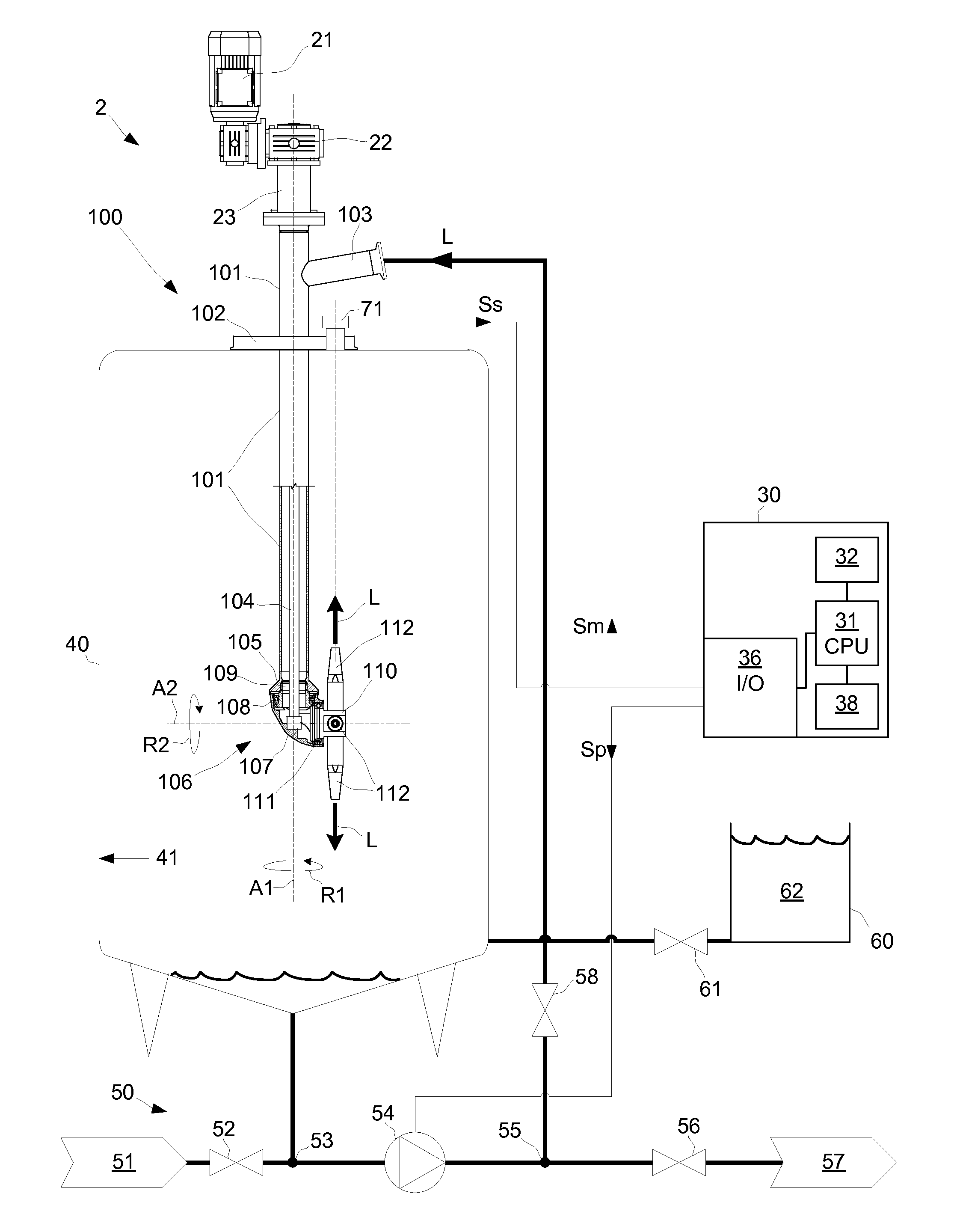
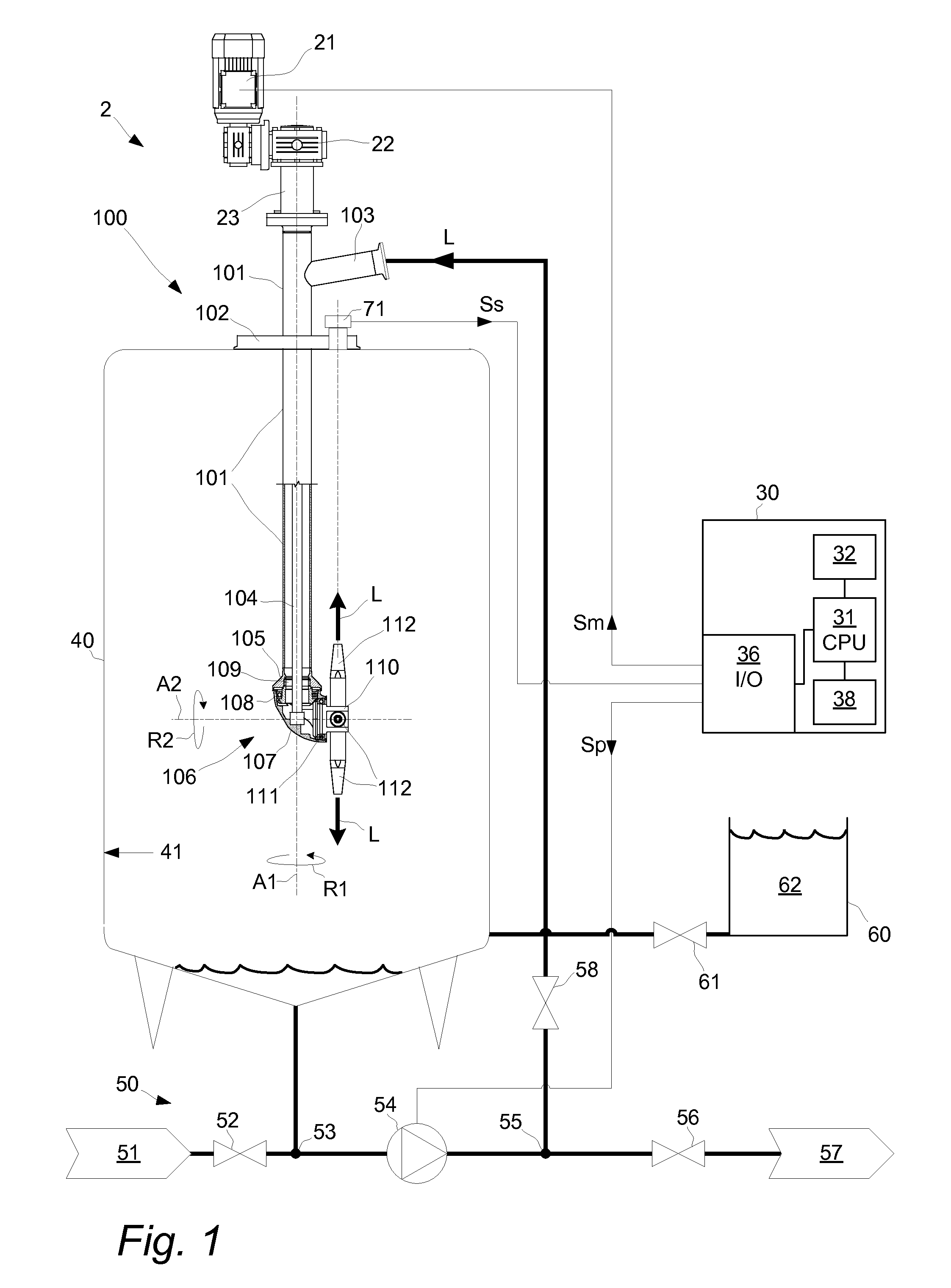
[0031]With reference to FIG. 1 an embodiment of a liquid ejection system 2 that is configured to eject a liquid L in a tank 40 is illustrated. The system 2 comprises a liquid ejection apparatus 100, a drive unit 21 for the liquid ejection apparatus 100, and a processing unit 30 that is configured to control the drive unit 21 and thereby a pattern for how liquid L is ejected from the liquid ejection apparatus 100 and into the tank 40.

[0032]The liquid ejection apparatus 100 has a pipe 101 that extends into the tank 40 via an opening in an upper part of the tank 40. The liquid ejection apparatus 100 has a flange 102 that provides a secure connection as well as a tight seal to the tank 40. An upper part of the pipe 101 that is outside the tank 40 has an inlet 103 for receiving the liquid L. A lower part of the pipe 101 that extends into the tank 40 has at its end a connection flange 105 to which a rotary head 106 is connected.

[0033]The rotary head 106 comprises a housing 107 that is rot...


PUM

PropertyMeasurementUnit
distanceaaaaaaaaaa
angleaaaaaaaaaa
angleaaaaaaaaaa

Abstract

A monitoring arrangement for a liquid ejection apparatus capable of ejecting liquid in a pattern on an interior surface of a tank, the monitoring arrangement comprising a sensor unit that generates a signal indicative of liquid coming into contact with the interior surface of the tank, and a processing unit configured to: receive the signal; retrieve a reference property that is indicative of liquid coming into contact with the interior surface; register, during a measuring period when the fluid nozzle ejects liquid, at least one current property of the signal; compare the current property with the reference property; and initiate, if the current property deviates from the reference property beyond a predetermined level, a message indicative of the deviation.

Description

TECHNICAL FIELD[0001]The invention relates to systems for internal cleaning of tanks and / or for mixing of contents in tanks, and in particular to techniques for monitoring the operation of such systems.BACKGROUND ART[0002]Liquid containment tanks or containers are used in a number of industrial processes such as food manufacturing, pharmaceutical manufacturing, chemical processing, material fermentation and so on. It is often critical to ensure that the interior of the tank is free of unwanted debris and contaminants. For example, a tank that is typically filled to a certain level may exhibit a “tub ring” about its interior circumference at the level to which the tank is most often filled. Also, various equipment within a tank, tank inlets and outlets etc. may trap sediment or debris that may later reenter the tank contents during use.[0003]Unwanted contaminants in the tank may negatively impact the quality of the finished product being manufactured or processed. Also, the interior ...

Claims


Application Information

Patent Timeline
Patent Type & Authority Applications(United States)
IPC IPC(8): G01N27/04B08B9/093
CPCB08B9/0936G01N27/041B08B9/0813B01F5/0231B05B3/066B01F5/10B05B13/0636B05B12/02B01F25/2122B01F25/50
Inventor FALSTER-HANSEN, HENRIKMADSEN, KARSTEN SCHACKBRANDT, CLAUS
Owner ALFA LAVAL CORP AB
Learn More