Adjustable Electrical-Power Outlet Strip

Inactive Publication Date: 2015-01-01
WANG CALVIN
View PDF5 Cites 39 Cited by
  • Summary
  • Abstract
  • Description
  • Claims
  • Application Information

AI Technical Summary

Benefits of technology

[0009]The adjustable electrical-power outlet strip (AEOS) is designed to be easily configured with a selectable quantity of a-c power receptac

Problems solved by technology

Plugging in this type of power supply will cover one or more of the other a-c receptacles rendering them unacceptable.
However, if more than one of these plugs must be plugged in, you

Method used


Image

  • Adjustable Electrical-Power Outlet Strip
  • Adjustable Electrical-Power Outlet Strip
  • Adjustable Electrical-Power Outlet Strip

Examples


Example

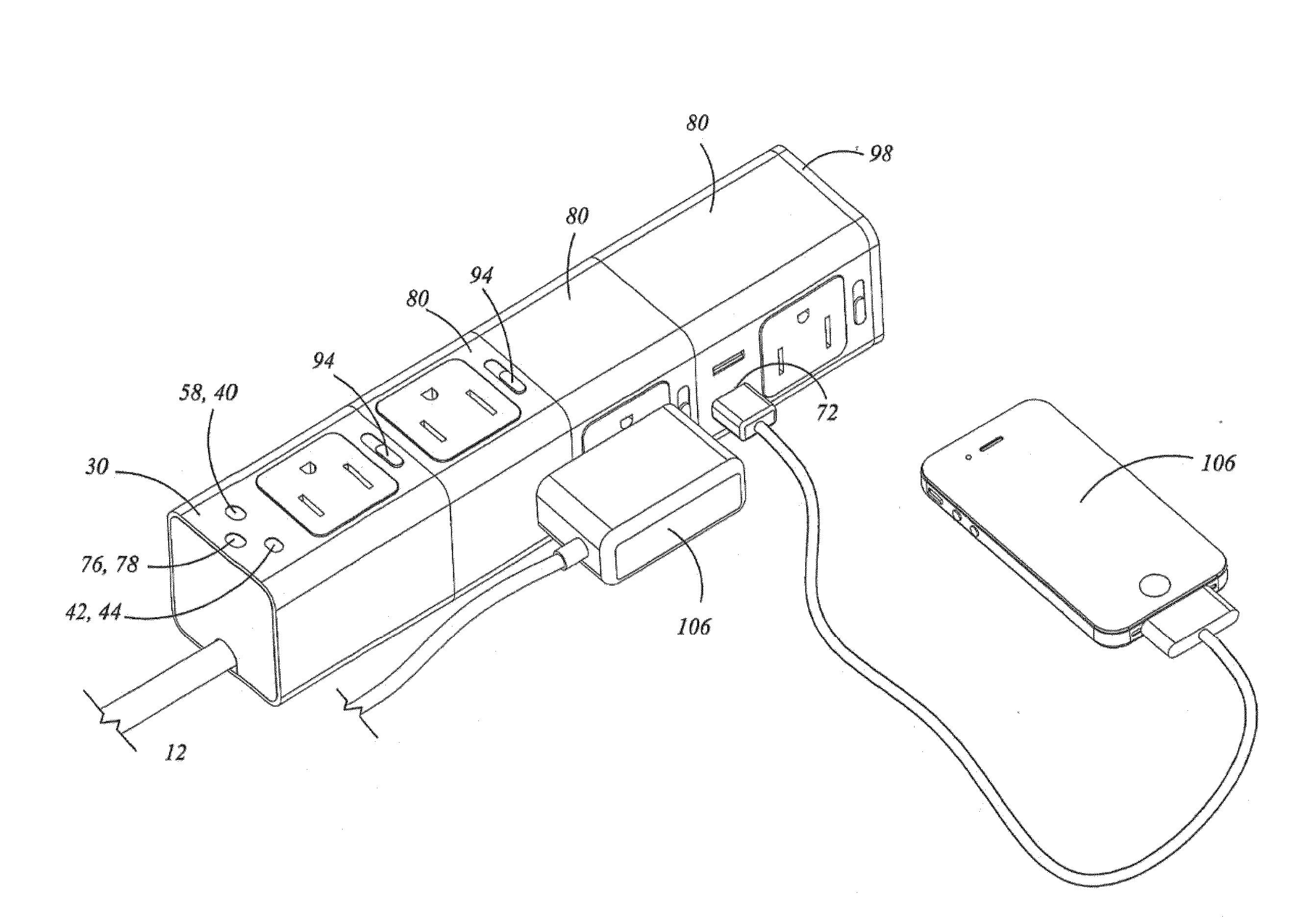
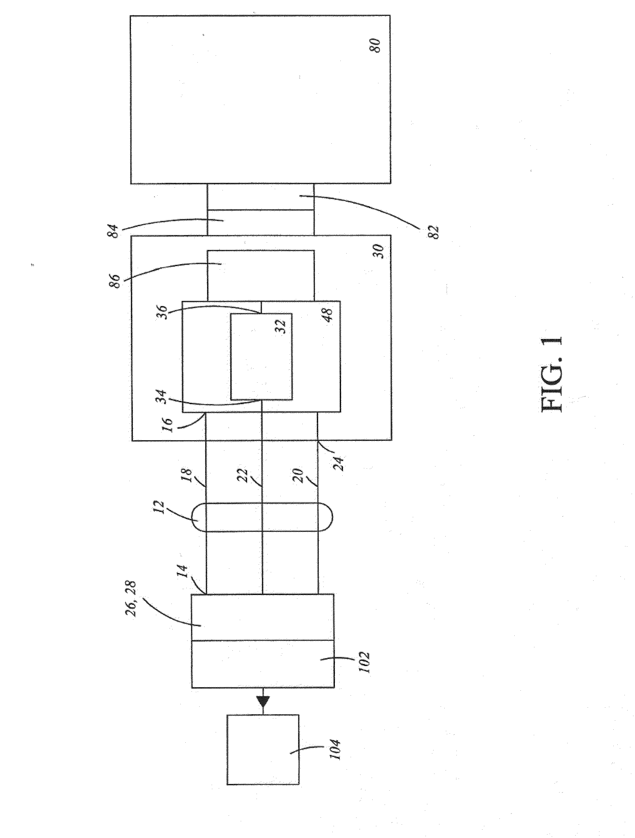
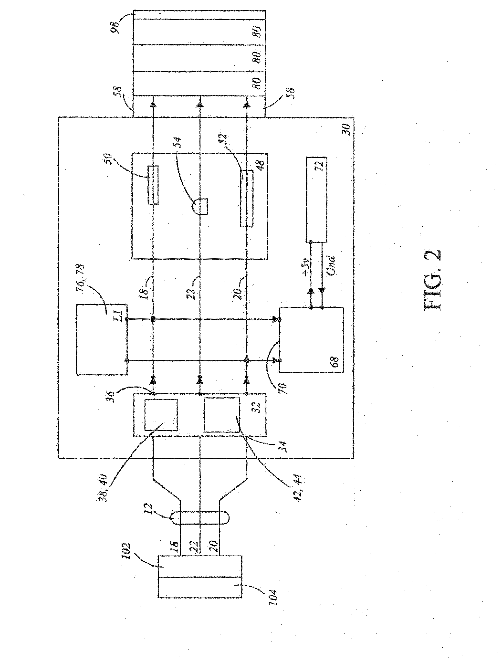
[0035]The best mode for carrying out the invention is presented in terms that disclose a preferred embodiment of an adjustable electrical-power outlet strip (AEOS). The AEOS allows a user to select any number of a-c power modules and to rotate and lock the modules to an optimum angular orientation. The preferred embodiment of the AEOS 10, as shown in FIGS. 1-11, is comprised of the following major elements: an a-c electrical power cord 12, a power input and control module 30, an a-c power module 80, a USB power supply 68 and a USB connector 72.

[0036]The a-c electrical power cord 12, as shown in FIG. 1, is comprised of an outer end 14, an inner end 24, a hot lead 18, a neutral end 20 and a ground lead 22. The outer end 14 of the cord 12 has attached an electrical plug 26 such as a three-prong plug 28. The plug 28 is inserted into an electrical receptacle 102 that is connected to a utility power source such as a 120-volt a-c power source 104, as also shown in FIG. 1.

[0037]The power in...


PUM


Abstract

An adjustable electrical-power outlet strip (AEOS) that allows a selected quantity of electrical receptacles to be connected on a single power strip. In addition to the electrical receptacles there is also a USB port that can be connected via a USB cable to charge an electronic component such as a cell phone. The AEOS is also designed to allow each of the connected power receptacles to be rotated to an optimum usable angle.

Description

TECHNICAL FIELD[0001]The invention generally pertains to electrical power outlet strips, and more particularly to a power outlet strip having a plurality of individual a-c power modules that can be selectively rotated to an optimum usable position.BACKGROUND ART[0002]AC electrical power strips are configured to increase the capacity and accessibility of a single electrical power receptacle. Most prior art power outlet strips include an elongated housing having an upper surface that include a power switch, a plurality of electrical power receptacles, and an end section from where extends a power cord that is connected to a single power receptacle attached to an a-c voltage source. When the power switch is turned on, power is simultaneously available at each of the power receptacles.[0003]A typical a-c power strip has all the a-c power receptacles located in a single straight line along the upper surface of the strip. This is sufficient if all of the a-c plugs are standard. However, i...

Claims


Application Information

Patent Timeline
IPC IPC(8): H01R13/70H02J3/00H01R13/04
CPCH01R13/70H02J3/00H01R13/04H01R24/78Y10T307/549H01R35/00H01R31/065H01R25/003Y04S20/222Y02B70/3225H02J7/0013H02J7/0045G06F1/16
Inventor WANG, CALVIN
Owner WANG CALVIN
Why Eureka
Try Eureka