
Conductive Thin Film Detector

a thin film detector and detector technology, applied in the direction of resistance/reactance/impedence, measurement devices, instruments, etc., can solve the problems of high false detection rate, severe degrade the antenna performance, and the inability of people to determine from visual observation whether a thin film is metallic, etc., to achieve accurate detection capability, less interference, and higher radio frequency

Active Publication Date: 2015-01-01
UNITED STATES OF AMERICA AS REPRESENTED BY THE FEDERAL BUREAU OF INVESTIGATION DOJ
View PDF3 Cites 5 Cited by
  • Summary
  • Abstract
  • Description
  • Claims
  • Application Information

AI Technical Summary

Benefits of technology

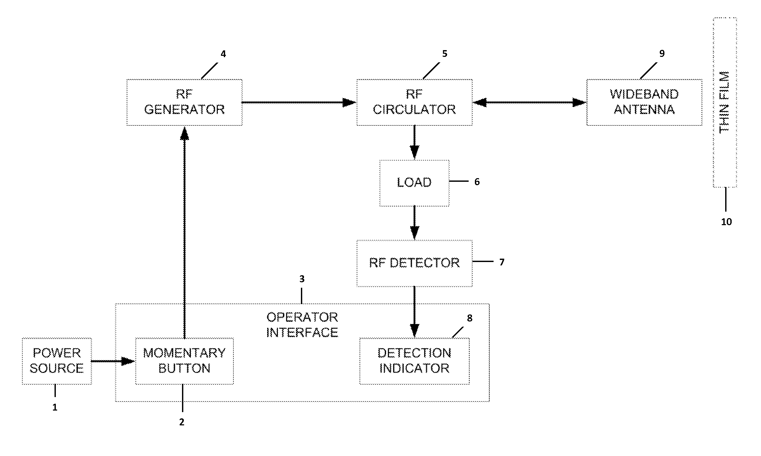
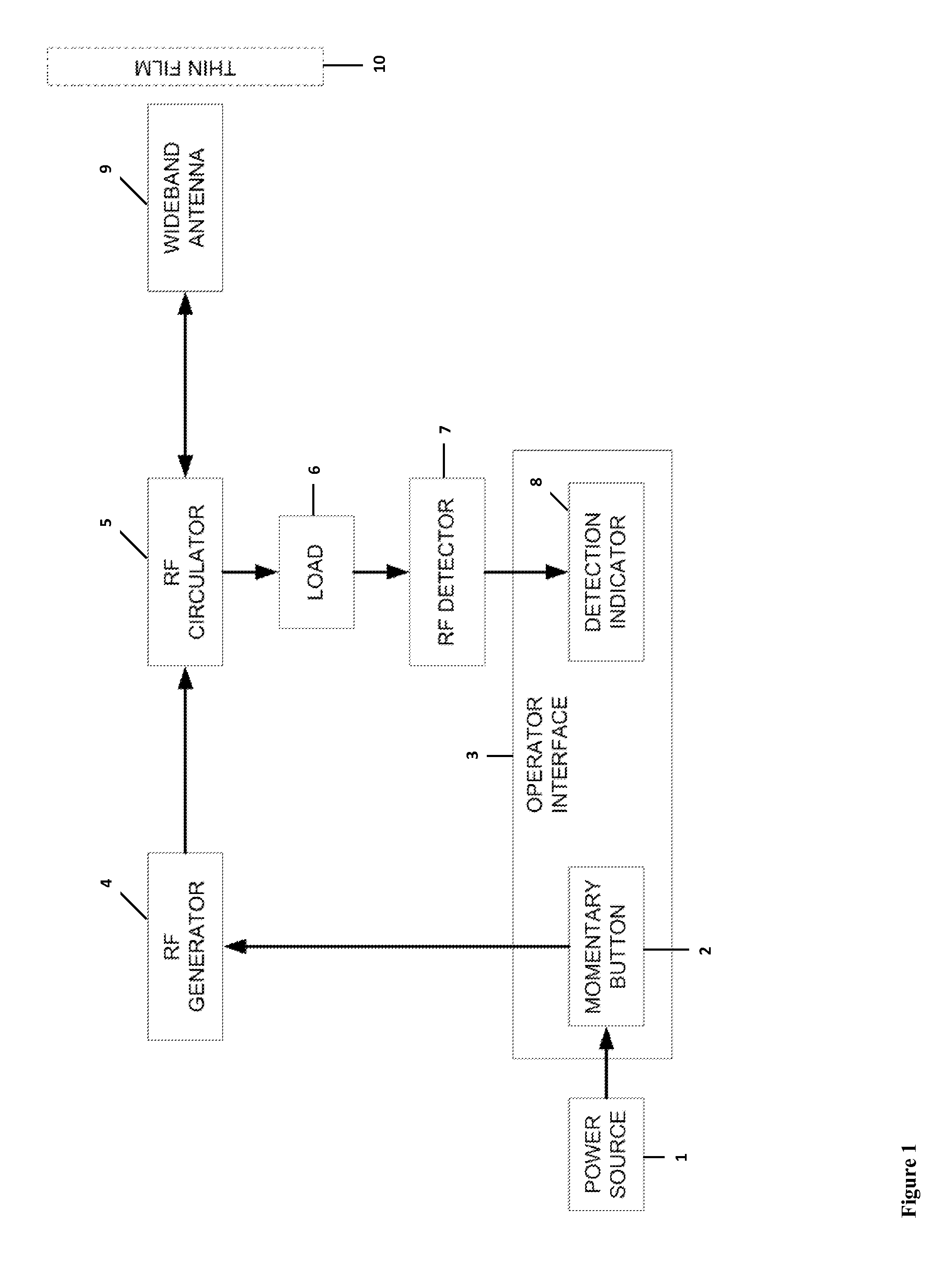
The invention is a metal detector that uses high radio frequencies to accurately detect metal objects. By using higher frequencies, the detector can have a smaller antenna which helps reduce interference from surrounding metallic objects and makes the detector easier to use. The detector also has a RF circulator, RF detector, and indicator that instantly tells the operator if there is conductive material present. This makes it easy for the operator to quickly determine if there is metal in the area being searched. Overall, the invention provides a high-quality, easy-to-use metal detector for improved efficiency and accuracy in metal detection.

Problems solved by technology

Because there are non-metallic thin films that appear metallic and metallic thin films that appear non-metallic, a person cannot determine from visual observation whether a thin film is metallic.
If the tinting is metallic, it will severely degrade the performance of an antenna.
For example, if BFO equipment is used to detect whether metal is incorporated into a thin film coated on a car window, the metal of the car would dominate the response from the BFO equipment and cause a high false detection rate.
Thus, the presence of a nearby large metal object, such as a car, would cause a high false detection rate.
Again, however, large metallic objects in relatively close proximity to the object being measured would generate a high false detection rate.

Method used


Image

  • Conductive Thin Film Detector
  • Conductive Thin Film Detector
  • Conductive Thin Film Detector

Examples


Embodiment Construction

[0071]This specification discloses embodiments that incorporate features of the invention. The disclosed embodiments merely exemplify the invention. The scope of the invention is not limited to the disclosed embodiments. The invention is defined by the claims appended hereto.

[0072]The embodiments described, and references in the specification to “one embodiment,”“an embodiment,”“an example embodiment,”“some embodiments,”“example,” etc., indicate that the embodiments described may include a particular feature, structure, or characteristic, but every embodiment may not necessarily include the particular feature, structure, or characteristic. Moreover, such phrases are not necessarily referring to the same embodiment. Further, when a particular feature, structure, or characteristic is described in connection with an embodiment, it is understood that it is within the knowledge of one skilled in the relevant art(s) to effectuate such feature, structure, or characteristic in connection wi...


PUM

PropertyMeasurementUnit
frequencyaaaaaaaaaa
frequencyaaaaaaaaaa
resonant frequencyaaaaaaaaaa

Abstract

The invention is directed to products used to detect and methods for detecting conductive materials in the presence of non-conductive materials, including non-conductive materials having dielectric properties. Specifically, the product is a conductive thin film detector, which is, preferably, a hand-held device designed to detect the presence of metal in, on, or under an object. This detection occurs even in the presence of non-conductive materials and other nearby conductive materials on objects that are not being tested. The device preferably comprises: a power source, such as a battery; a method for activation, such as a press button; the necessary components to send and receive a radio frequency, e.g., a radio frequency generator, an antenna, and a radio frequency detector; and an indicator, such as a light or a meter, to, for example, indicate the strength of the radio frequency signal received.

Description

STATEMENT OF GOVERNMENT INTEREST[0001]The invention described herein was invented by employees of the United States Government and may be manufactured and used by or for the government for governmental purposes without the payment of any royalties.BACKGROUND[0002]1. Field[0003]The field of the present invention relates to novel methods for detecting and products used to detect the presence of conductive materials, including in the presence of non-conductive materials, wherein the non-conductive materials may have dielectric properties. In addition, the methods and products of the invention detect the presence of specific conductive materials even in the presence of other conductive materials nearby.[0004]2. Background[0005]Conductive Thin Films[0006]Conductive materials include metals, electrolytes, and plasmas, as well as certain non-metallics, such as graphite and conductive polymers. Often, conductive materials are formed into a thin film and coated onto glass or ceramics. For ex...

Claims


Application Information

Patent Timeline
Patent Type & Authority Applications(United States)
IPC IPC(8): G01R27/02
CPCG01R27/02G01N27/02G01V3/12G01S13/04
Inventor BUXTON, CAREY G.HUGGINS, JOHN SCOTT
Owner UNITED STATES OF AMERICA AS REPRESENTED BY THE FEDERAL BUREAU OF INVESTIGATION DOJ
Learn More