
System and Method for Network Uplink Measurement Based Operation Using UE Centric Sounding

a network uplink and centric sounding technology, applied in the field of wireless communications, can solve the problems of multi-point transmission experiencing timing advance (the length of time), complicated dl reference signal design and significant signaling overhead, etc., and achieve the effect of slow link adaptation, and enabling uplink measurement based operation and control

Active Publication Date: 2015-01-01
HUAWEI TECH CO LTD
View PDF4 Cites 81 Cited by
  • Summary
  • Abstract
  • Description
  • Claims
  • Application Information

AI Technical Summary

Benefits of technology

The present invention provides a new structure and method for carrying out certain purposes. The technical effects of the invention include providing a more efficient and effective solution for the described problem, improving the accuracy and precision of the process, and reducing the time and cost required for the task. The invention can be easily modified and adapted for different needs and applications. Overall, the invention offers a unique solution to achieve the desired results.

Problems solved by technology

This requires each cell to provide dedicated DL reference signals, which leads to complicated DL reference signal design and significant signaling overhead, and other issues for current or future wireless network technologies, such as in heterogeneous network (HetNet) where Pico cells may not provide reference signals.
Further, using DL-based measurement, UL coordinated multi-point (CoMP) transmission may experience timing advance (the length of time a signal takes to reach TPs from a UE) issues within serving TPs.
Another issue is that a dynamic (e.g., upon demand) TP optimization scheme requires frequent UE measurement and feedback, which is challenging for DL pilot design with more antennas.

Method used


Image

  • System and Method for Network Uplink Measurement Based Operation Using UE Centric Sounding
  • System and Method for Network Uplink Measurement Based Operation Using UE Centric Sounding
  • System and Method for Network Uplink Measurement Based Operation Using UE Centric Sounding

Examples


Embodiment Construction

[0025]The making and using of the presently preferred embodiments are discussed in detail below. It should be appreciated, however, that the present invention provides many applicable inventive concepts that can be embodied in a wide variety of specific contexts. The specific embodiments discussed are merely illustrative of specific ways to make and use the invention, and do not limit the scope of the invention.

[0026]Current terminal device measurement based design may not efficiently support future radio access virtualization where there is no one-to-one association between transmit point and terminal device. Specifically, the device needs to know an index or ID of a TP in order to perform measurement based on DL reference signals. In addition, denser TP deployment is expected in future networks, supporting more terminal devices. Thus, there may be significant increase of DL-measurement reference signal overhead and terminal device report overhead.

[0027]To effectively solve at leas...


PUM


Abstract

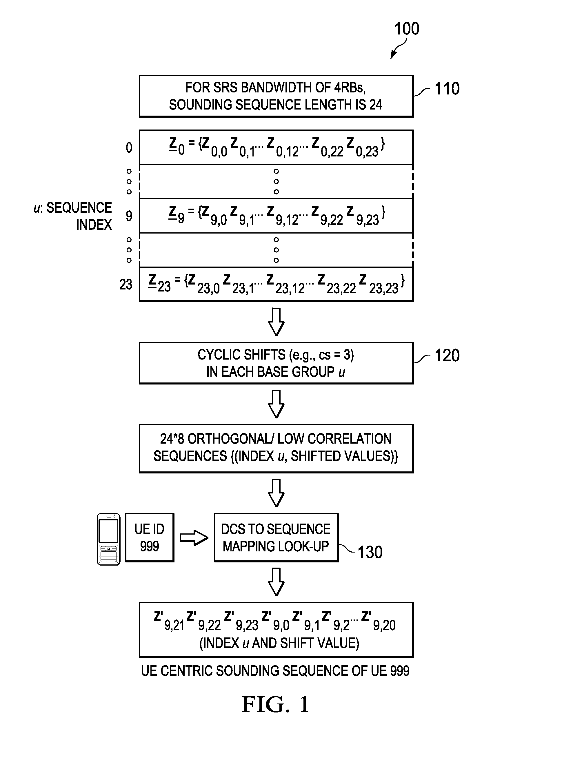
Embodiments are provided for uplink measurement based mechanism and control using user equipment (UE) centric sounding signals. The mechanism provides an alternative to DL-measurement dominated system control. Based on UL-measurements at TPs, the network obtains knowledge of users' channel and timing information, traffic, and interference, and is thus able to perform better control, including TP and UE clustering and optimization, and power control and link adaptation. In an embodiment method, a TP receives one-to-one mapping information indicating a plurality of UE IDs and a plurality of sounding channels assigned to the corresponding UE IDs. When the TP detects a sounding reference signal (SRS) from a UE, the TP is able to identify the UE using the detected SRS and the one-to-one mapping information. The TP then obtains measurement information for the identified UE, enabling better control and communications for uplink and downlink transmissions between multiple TPs and the UE.

Description

TECHNICAL FIELD[0001]The present invention relates to the field of wireless communications, and, in particular embodiments, to a system and method for network uplink measurement based operation using UE-centric uplink sounding.BACKGROUND[0002]In current cellular or wireless technologies, the system controls are dominated by downlink (DL) measurements (UE measure and report). For example, the clustering or grouping of transmission points (TPs) for downlink (DL) and uplink (UL) transmissions is typically established based on user equipment (UE) measurements from DL reference signals, e.g., from each cell. This requires each cell to provide dedicated DL reference signals, which leads to complicated DL reference signal design and significant signaling overhead, and other issues for current or future wireless network technologies, such as in heterogeneous network (HetNet) where Pico cells may not provide reference signals. Further, using DL-based measurement, UL coordinated multi-point (...

Claims


Application Information

Patent Timeline
Patent Type & Authority Applications(United States)
IPC IPC(8): H04W24/08H04W72/04
CPCH04W72/0413H04W24/08H04B7/024H04B7/0413H04B7/0686H04L5/0007H04L5/0064H04L5/0051Y02D30/70H04L5/0035
Inventor SENARATH, GAMINIAU, KELVIN KAR KINMA, JIANGLEIZHANG, LIQING
Owner HUAWEI TECH CO LTD
Learn More