
Air purifying apparatus using microwaves

a technology of air purification apparatus and microwave, which is applied in the direction of dispersed particle separation, separation process, disinfection, etc., can solve the problems of increasing the maintenance cost of the purifying apparatus, the inability to efficiently purify the air, and the odor of polluted air, so as to improve energy efficiency and improve the effect of air purification efficiency and ensuring safety

Active Publication Date: 2015-01-01
LEE YEON SU +1
View PDF1 Cites 7 Cited by
  • Summary
  • Abstract
  • Description
  • Claims
  • Application Information

AI Technical Summary

Benefits of technology

The air purifying apparatus using microwves described in this patent text combats contaminated air by heating it at a high temperature to remove the contaminants. A ceramic filter is used to improve energy efficiency and safety, and a shielding member prevents leakage. The apparatus improves air purifying efficiency and filtering efficiency, and does not require a heater in the air passage. Microwaves are supplied to the ceramic filter in a longitudinal direction to improve filtering efficiency of the contaminated air.

Problems solved by technology

However, as can be seen from the air purifying apparatus, which includes various filters, such filter-type air purifying apparatus installed in a conventional duct tends to put a bigger emphasis on filtering polluted materials such as dust, and thus, it is not suitable for purifying odor, soot, bacteria, and the like contained in polluted air.
Further, the filter-type purifying apparatus increases maintenance costs, as filters are needed to be cleaned and replaced on a regular basis, and if not properly cleaned, the filters may not purify air efficiently.
However, the collector also has problems in that a combustion heater, which is heated by electric heat of heat wires, loses heat to the outside, such that combustion efficiency may be reduced and safety may not be guaranteed.
Further, in such collector, the combustion heater is not precisely structured, and due to a short length of stay in the combustion heater, contaminated air does not stay long enough to be burned properly, such that filtering efficiency may be reduced.
In addition, a water tank for filtering burned ashes may not be installed in a limited space, leading to an increased cost of initial installation, and it would be cumbersome to regularly maintain the water tank.

Method used


Image

  • Air purifying apparatus using microwaves
  • Air purifying apparatus using microwaves
  • Air purifying apparatus using microwaves

Examples


Embodiment Construction

[0024]The following description is provided to assist the reader in gaining a comprehensive understanding of the methods, apparatuses, and / or systems described herein. Accordingly, various changes, modifications, and equivalents of the methods, apparatuses, and / or systems described herein will be suggested to those of ordinary skill in the art. Also, descriptions of well-known functions and constructions may be omitted for increased clarity and conciseness.

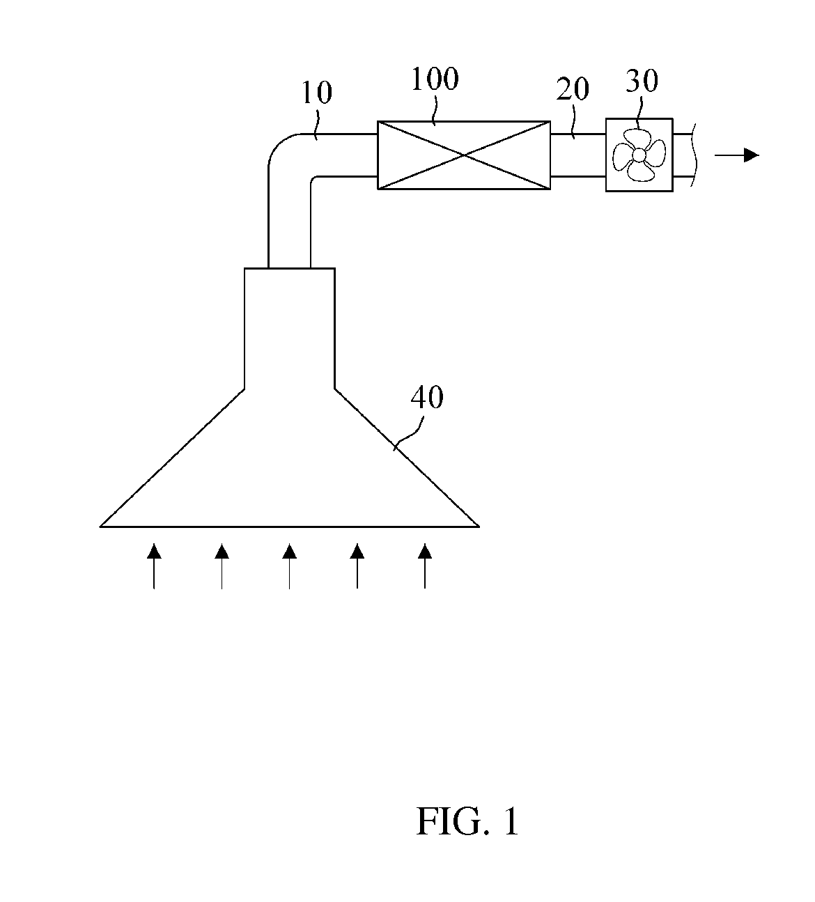
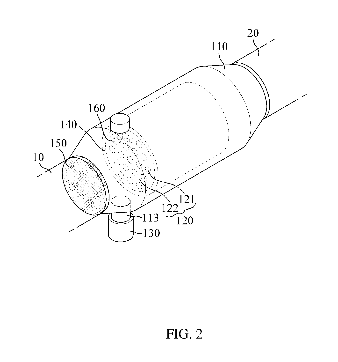
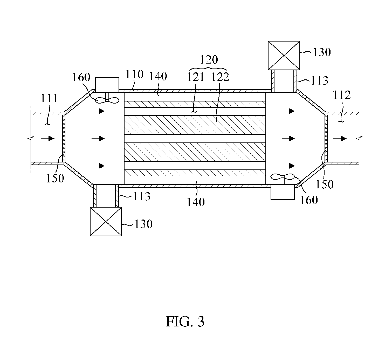
[0025]According to examples illustrated in FIGS. 1 to 4, an air purifying apparatus is provided to remove contaminants, such as soot and the like, by burning contaminated air while passing the contaminated air through a filter heated by microwaves.

[0026]It should be noted that the air purifying apparatus according to an exemplary embodiment may be installed and used alone, or may be used by being installed on a path where air flows such as ducts 10 and 20. Particularly, in ducts 10 and 20, the air purifying apparatus is installed ...


PUM

PropertyMeasurementUnit
frequencyaaaaaaaaaa
heataaaaaaaaaa
combustion efficiencyaaaaaaaaaa

Abstract

In an air purifying apparatus for removing contaminants, such as soot and the like, by burning contaminated air while passing the contaminated air through a filter heated by microwaves, the apparatus includes: a housing, which is hollow, and comprises an inlet on one side and an outlet on the other side; a ceramic filter of a longitudinal material, which is arranged in the housing in a longitudinal direction of the housing, and includes a plurality of partition walls formed so that a flow path where contaminated air flows may be divided in plurality; and a microwave generator configured to generate microwaves to be supplied to one end surface of the ceramic filter in a longitudinal direction thereof to heat the one end surface of the ceramic filter in the longitudinal direction.

Description

CROSS-REFERENCE TO RELATED APPLICATION(S)[0001]This application claims priority from Korean Patent Application No. 10-2013-0074017, filed on Jun. 26, 2013, in the Korean Intellectual Property Office, the entire disclosure of which is incorporated herein by reference for all purposes.BACKGROUND[0002]1. Field[0003]The following description generally relates to an air purifying apparatus using microwaves, and more particularly to an air purifying apparatus, which is installed in a duct where air flows, and removes contaminants by burning contaminated air while passing the contaminated air through a filter heated by microwaves.[0004]2. Description of the Related Art[0005]Most homes or businesses are provided with basic ventilation systems to forcibly remove indoor contaminated air to the outside. More specifically, a range hood mounted above a cooking counter or a ventilator mounted on a ceiling or a wall draws in contaminated air and releases the air to the outside through a duct where...

Claims


Application Information

Patent Timeline
Patent Type & Authority Applications(United States)
IPC IPC(8): A61L9/16
CPCA61L9/16A61L9/00B01D49/00B01D53/32B01D53/34
Inventor LEE, YEON, SU
Owner LEE YEON SU
Learn More