Devices and methods of function-based control in automation systems

Inactive Publication Date: 2015-01-01
GREEN EDGE TECH
View PDF6 Cites 112 Cited by
  • Summary
  • Abstract
  • Description
  • Claims
  • Application Information

AI Technical Summary

Benefits of technology

[0004]The present disclosure is generally directed toward improving functionality of an automation system by associating or mapping identified appliances and power delivery devices to switches or other actuators that have defined functions. The switches

Problems solved by technology

Further, if reprogramming is not done correctly, modifying the control of one device may disrupt the entire au

Method used


Image

  • Devices and methods of function-based control in automation systems
  • Devices and methods of function-based control in automation systems
  • Devices and methods of function-based control in automation systems

Examples


Embodiment Construction

[0022]Reference now will be made in detail to embodiments of the present disclosure, examples of which are illustrated in the accompanying drawings. Wherever possible, the same reference numbers will be used throughout the drawings to refer to the same or like parts and / or components.

Overview

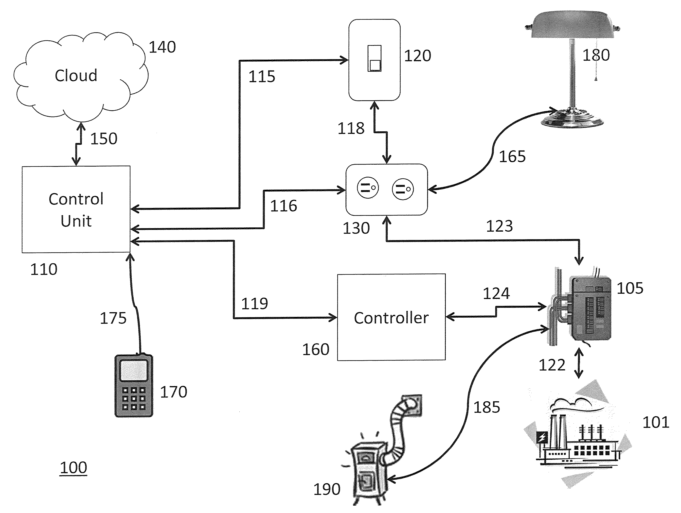
[0023]An automation system, e.g., a home automation system, generally may include one or more switches and one or more outlets (or other suitable power delivery components), with the user desiring which outlet or outlets are controlled by the switch(es). Existing X10 devices require the user to manually set an address on the switch and the outlet, an outlet would respond to a switch with an identical address enabling or disabling power to the outlet on command of the identically addressed switch.

[0024]Embodiments of the present disclosure include, among other things, an automation system. Examples of suitable systems include those described in U.S. application Ser. No. 13 / 672,534, filed Nov. 8, ...


PUM


Abstract

The present disclosure is generally directed to automation systems and methods of use thereof to control devices. More particularly, the present disclosure includes systems including function-based controls and methods of assigning function-based controls to allow a user to add, relocate, and/or remove a device without requiring the user to reprogram the system.

Description

FIELD OF THE INVENTION[0001]Embodiments of the present disclosure are generally directed to systems, devices, and methods for automating the determination of which devices (e.g., appliances or power delivery components) may be controlled, e.g., by a switch or other suitable actuator, in an automation system. More particularly, the present disclosure includes methods of detecting a function of a switch and determining a set of appliances or power delivery components to be controlled, e.g., by activating a control.BACKGROUND OF THE INVENTION[0002]Existing home automation control solutions, such as products supporting the X10 protocol, require a determination of which devices to be controlled be made a priori. If an appliance is added, removed, or moved, then the user must reprogram the home automation system to account for the change. The user also must maintain and manually update a list of which devices are associated with a control to account for any subsequent changes. Further, if...

Claims


Application Information

Patent Timeline
IPC IPC(8): G05B15/02
CPCG05B15/02G05B2219/2642G05B19/0426G05B2219/25086
Inventor STEELE, SCOTT A.ALBERTH, JR., WILLIAM P.HARTSFIELD, DAVID K.RICE, WILLIAM D.
Owner GREEN EDGE TECH
Why Eureka
Try Eureka