Coil and serpentine bent fin tube condensing heat exchanger

a heat exchanger and coil technology, applied in water heaters, fluid heaters, lighting and heating equipment, etc., can solve the problems of reducing heat exchanging efficiency, condensing boilers can not only use sensible heat in the flue but also latent heat, and the flue temperature of conventional boilers is very high, so as to improve the heat exchange structure, increase the heat exchange surface and efficiency of the flue side, and increase the temperature of the inlet air

Active Publication Date: 2015-01-08
SUZHOU CQ HEAT EXCHANGER
View PDF7 Cites 8 Cited by
  • Summary
  • Abstract
  • Description
  • Claims
  • Application Information

AI Technical Summary

Benefits of technology

[0013]The technical problems that need to be solved include: dead zones of flue flow and insufficient heat exchanging because of the poor heat exchanger structure design; increase the flue side heat transfer surface and efficiency by improving the heat transfer structure; to make the size smaller under the same heat transfer output; to integrate an air pre-heater into the heat exchanger to get the opportunity of third heat exchanging; and increase the temperature of the inlet air and decrease the flue temperature further.

Problems solved by technology

The conventional boiler has very high flue temperature because of the limitation of the structure.
However, condensing boiler can not only use sensible heat in the flue but also the latent heat because of the low flue temperature.
It decreases the heat exchanging efficiency.
The heat exchanger is not designed to absorb the sensible and latent heat when the water vapor condensing, and there is no condensate.
The life the condensing boiler will be shortened significantly if the carbon steel or cast iron is used because the boiler generates a lot of acid condensing water.
It is a proven technology to make cast aluminum heat exchanger, but the capacity is limited.
It is very difficult to make the big cast aluminum parts.
Typically, the bigger the cast, the higher the mold cost, the more complex manufacturing process and the higher scrap rate.
Because there are a lot of components involved in the manufacture of heat exchangers, manufacturing many sizes of heat exchangers is not good practice for mass production.

Method used


Image

  • Coil and serpentine bent fin tube condensing heat exchanger
  • Coil and serpentine bent fin tube condensing heat exchanger
  • Coil and serpentine bent fin tube condensing heat exchanger

Examples


Embodiment Construction

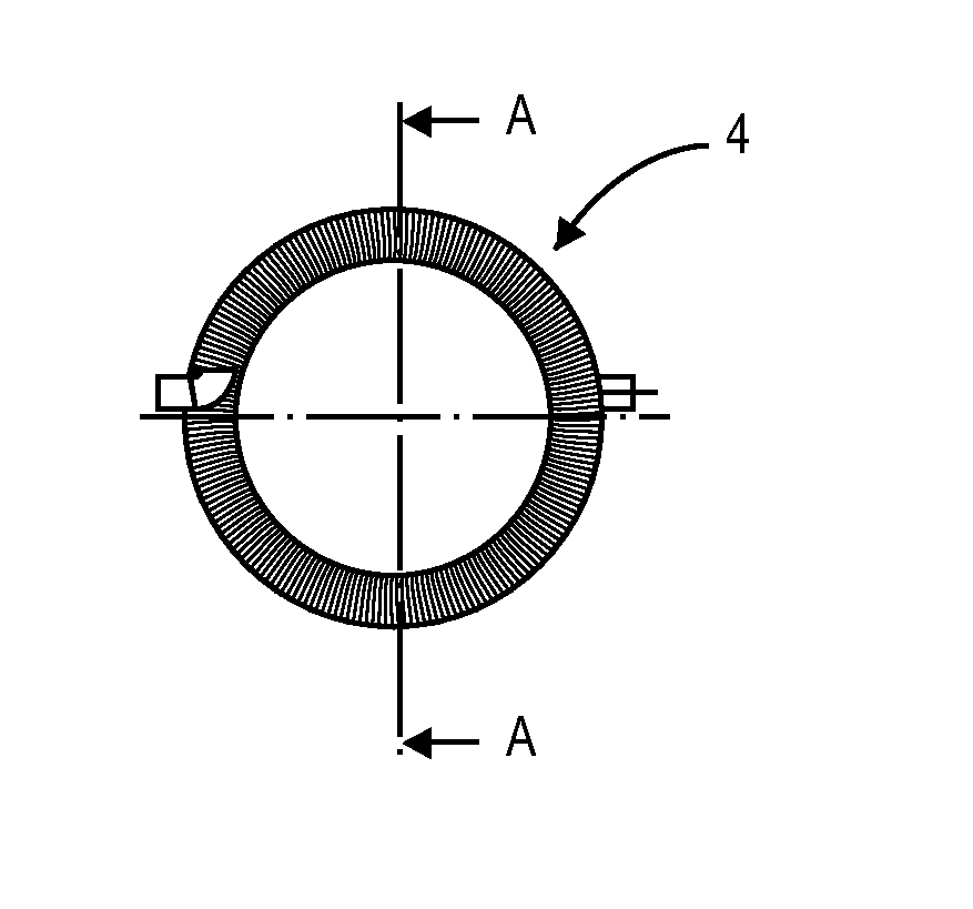
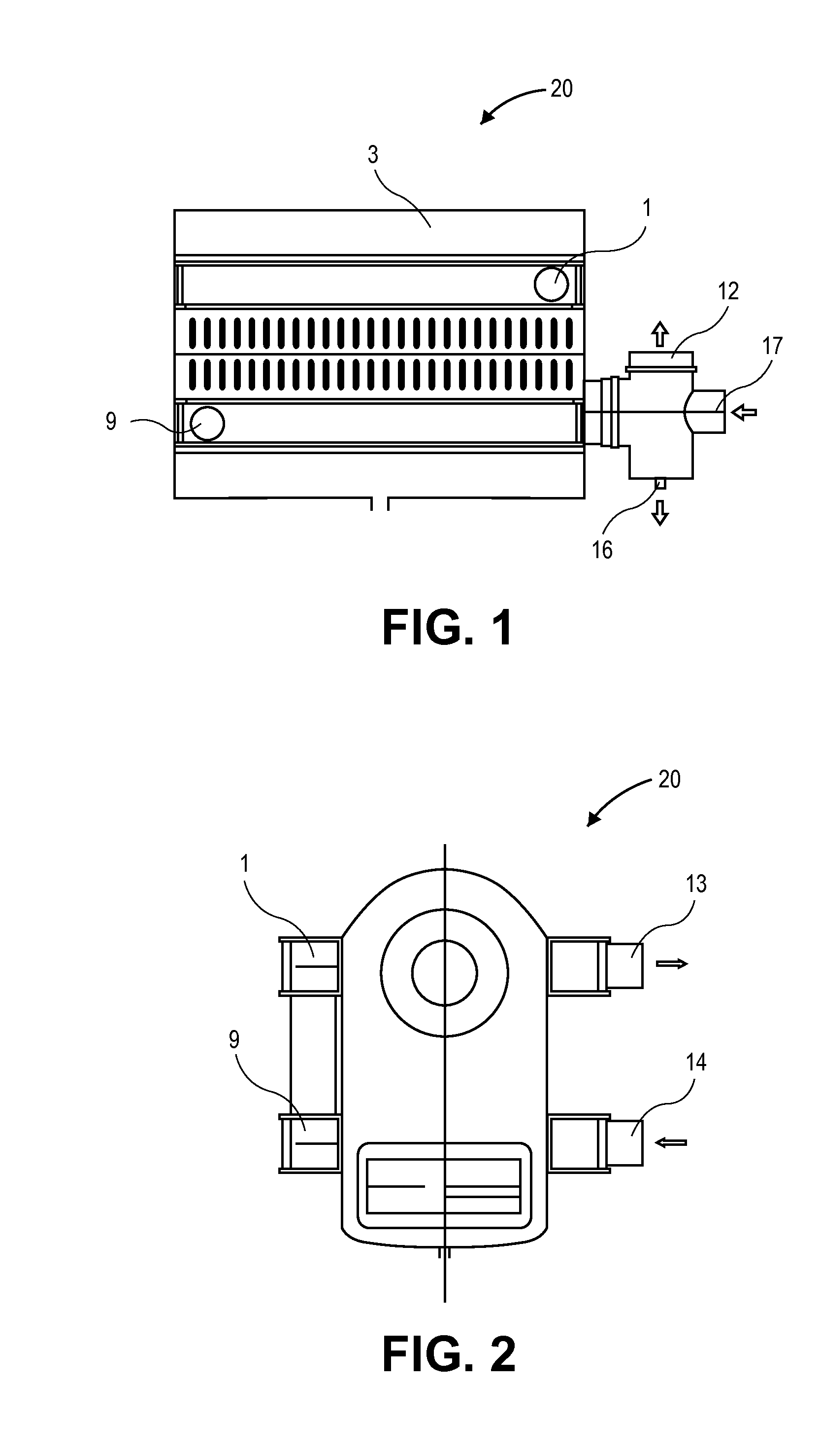
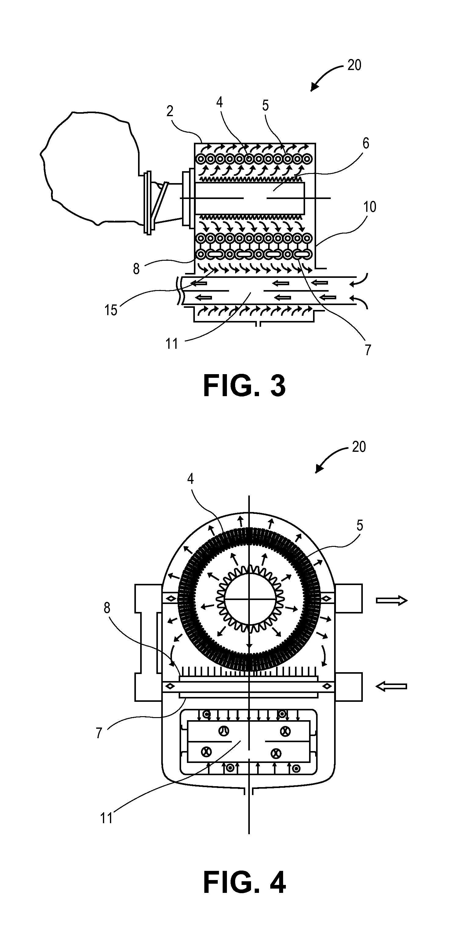
[0042]Various embodiments of the present invention provide for an increase the heat exchanger efficiency of a heat exchanger. In embodiments of this invention the heat exchanger has a counter flow design with two-stage heat exchanger. The burner is on the top and the flue outlet on the bottom. After burning, the combustion flue gas flows through the group of fin tubes around the burner and flue baffles located outside these tubes first, then it flows through the serpentine bent fin tubes above the flue channel and the flue baffles under these tubes. Thereafter, the flue gas flows out from the flue outlet along the flue channel and counter flow with inlet air. The water inlet is close to the flue outlet at the bottom, and the water outlet is on the top of the heat exchanger. The water flows through inlet, fin tubes, and the cavities connected to the upper and lower fin tube bundles at both ends, such as front and rear water manifolds, and then out from the outlet. The boiler water su...


PUM


Abstract

A heat exchanger for supplying heat includes a housing, a bundle of helical fin-coil tubes, and a flue channel. The housing includes a burner, a water inlet, a water outlet and a flue gas outlet. The burner is disposed on a top portion of the housing and connected to an air/gas mixture unit. The bundle of helical fin-tube coils is disposed tightly, circularly, and coaxially around the burner. The flue channel is disposed below the burner and is formed by a plurality of serpentine bent fin-tube coils. A flow of flue gas vents from the flue channel to the flue gas outlet. The water inlet is connected to the plurality of serpentine bent fin-tube coils which forms the flue channel below the burner. The plurality of serpentine bent fin-tube coils below the burner are connected to the bundle of helical fin-tube coils. The bundle of helical fin-tube coils are connected to the water outlet.

Description

CROSS REFERENCE TO RELATED APPLICATIONS[0001]This application is a continuation of and claims priority to PCT / CN2013 / 083873, filed on Sep. 21, 2013, which claims priority to CN 201210355221.1, filed on Sep. 21, 2012, the disclosures of which are incorporated herein by reference in their entireties.FIELD OF THE INVENTION[0002]This invention relates generally to equipment in the heating industry field. More particularly, the invention is related to a forced convection helical and serpentine fin tube condensing heat exchanger for supplying heat.BACKGROUND OF THE INVENTION[0003]As far back as the Middle East oil crisis in the in 20th century, to save the energy, the high efficient condensing boiler was developed in Europe. The outstanding feature of the boiler is that the efficiency is 10% higher than the conventional boiler. Abundant water vapor in the flue is condensed and releases the latent heat of vaporization because the flue temperature can be decreased to below the dew point. Th...

Claims


Application Information

Patent Timeline
Patent Type & Authority Applications(United States)
IPC IPC(8): F24H1/12F24H8/00
CPCF24H8/006F24H1/124F24H1/43F24H9/0084F24H1/41F24H8/00F24H9/0026F28D7/024F24H1/445Y02B30/00
Inventor CUI, SHUQING
Owner SUZHOU CQ HEAT EXCHANGER
Why Eureka
Try Eureka