Method for reducing rag layer volume in stationary froth treatment

a technology of stationary froth treatment and rag layer volume, which is applied in the petroleum industry, liquid hydrocarbon mixture production, etc., can solve the problems of undesirable solids and water content of bitumen, and achieve the effects of reducing the amount of water in the rag layer volume, and improving the quality of the splitter

Inactive Publication Date: 2015-01-08
SYNCRUDE CANADA LTD
View PDF2 Cites 2 Cited by
  • Summary
  • Abstract
  • Description
  • Claims
  • Application Information

AI Technical Summary

Benefits of technology

[0012](1) Mixing of the rag layer that forms in a separation vessel significantly reduces the rag layer volume. In particular, rag layer mixing alone significantly reduces rag layer volume compared to feed (e.g., scrubber feed) mixing alone. Gentle or mild mixing is sufficient. The combined use of rag layer mixing and scrubber feed mixing is more effective in reducing the rag layer volume compared to either rag layer mixing alone or feed mixing alone.
[0024]In one embodiment, mixing reduces the rag volume in a polisher vessel at naphtha diluent to bitumen ratio of about 0.7.

Problems solved by technology

However, these treatment processes still result in bitumen often containing undesirable amounts of solids and water.

Method used


Image

  • Method for reducing rag layer volume in stationary froth treatment
  • Method for reducing rag layer volume in stationary froth treatment
  • Method for reducing rag layer volume in stationary froth treatment

Examples


example 1

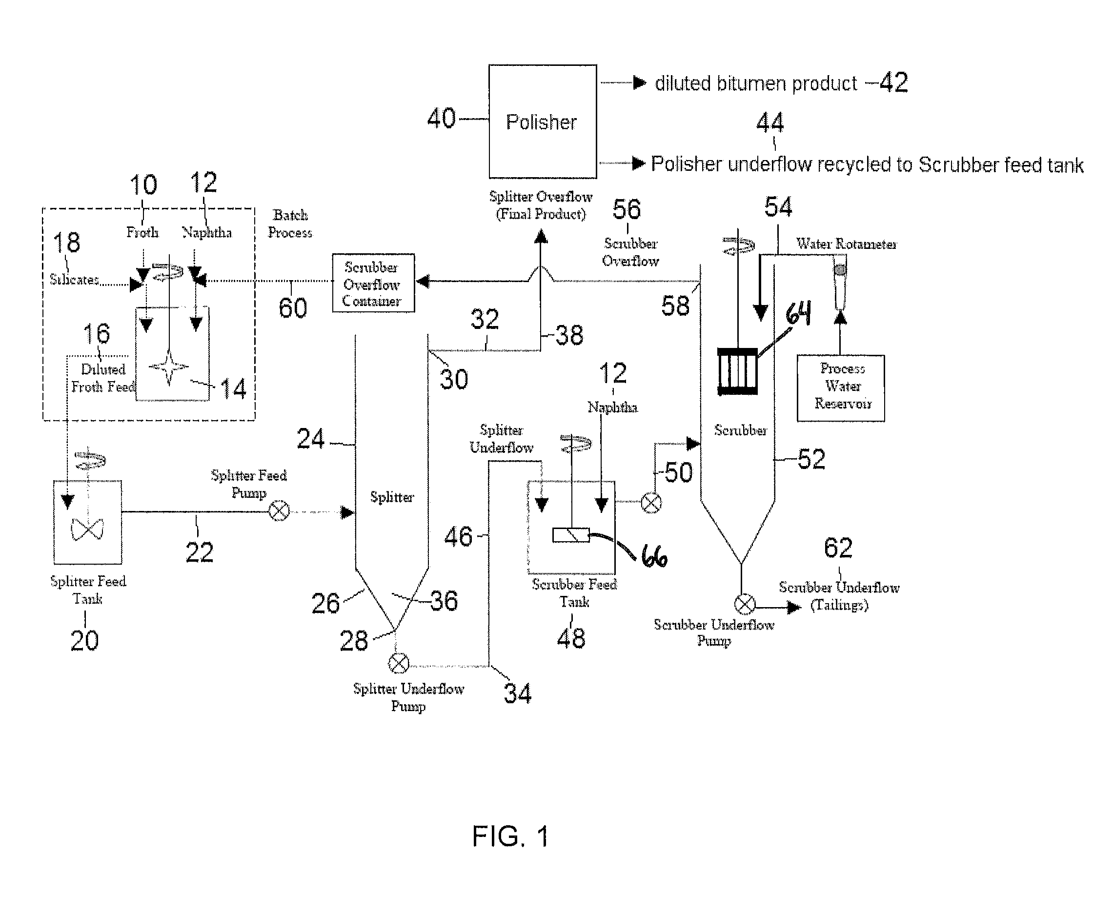
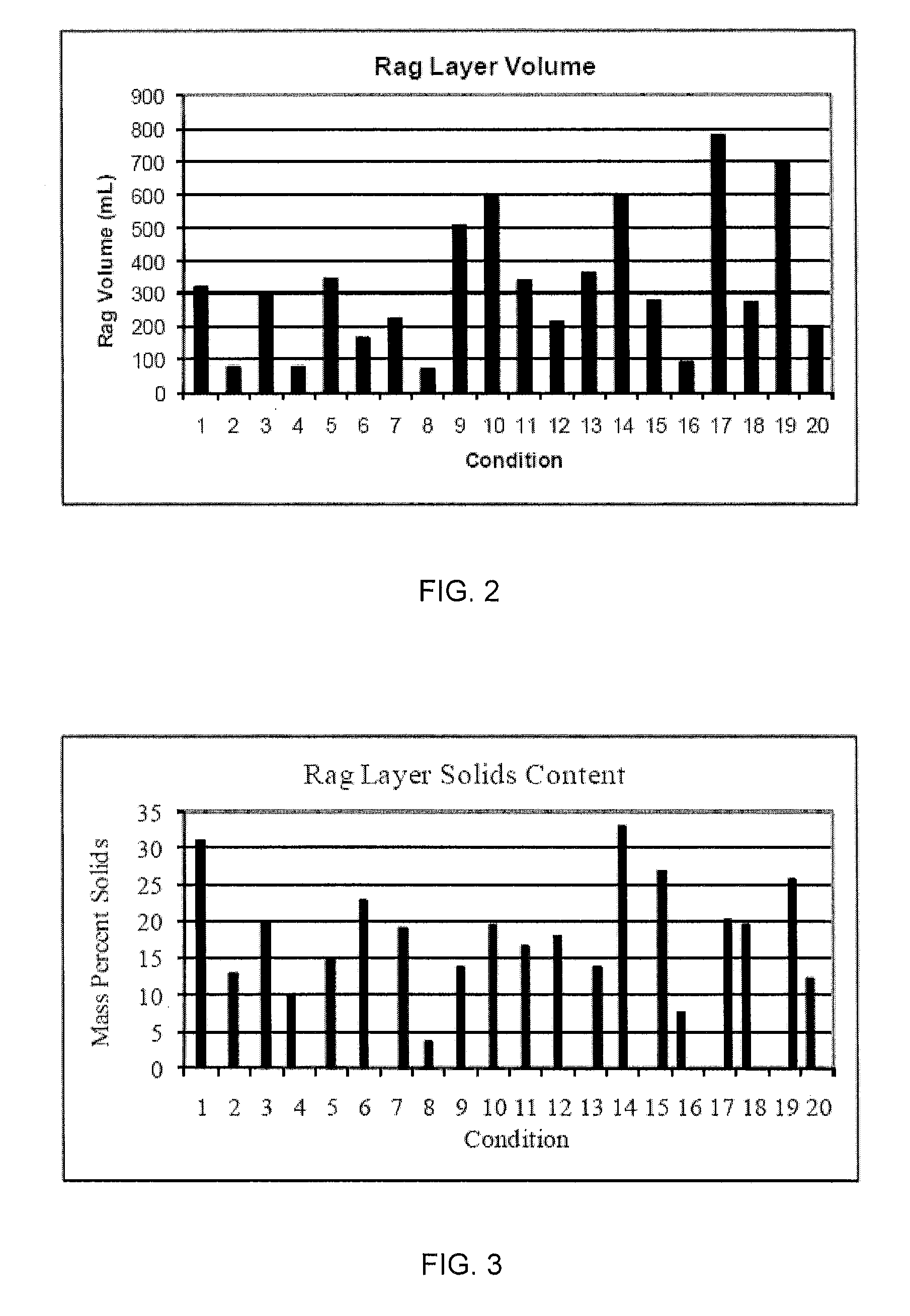
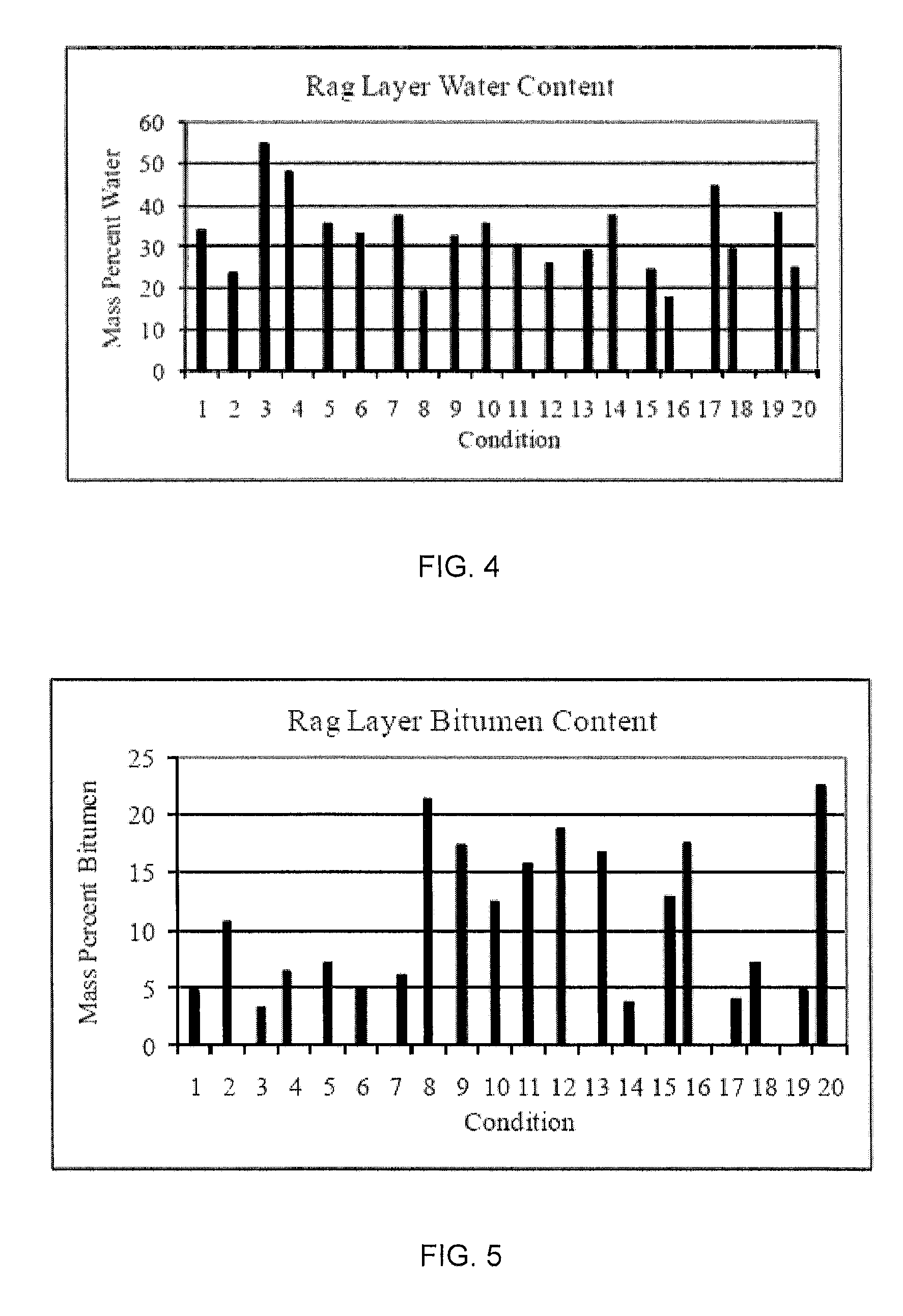
[0044]The flow sheet used for the evaluation of the rag volume reduction is essentially the same as that shown in FIG. 1 except that the polisher vessel was omitted to enable timely experimentation. Five variables including silicates concentration, water addition to rag layer, rag layer agitation, scrubber feed agitation and scrubber N / B ratio were evaluated using a 25-1 fractional factorial design resulting in 16 different experimental run conditions. Table 1 summarizes the range of the independent variables and the test matrix. In addition, Table 1 includes repeat conditions and an additional run using higher rag layer agitation (Condition No. 18), resulting in a total of 20 runs completed.

TABLE 1Test MatrixWaterRag LayerSilicatesAdditionAgitationScrubber FeedScrubberConditionwt. %(g / min)RPMRPMN / B1000700>6201652700>630.1052700>640.1160700>650.116521300>6600521300>6701601300>6800527009016070010000130011016521300120.10521300130.11601300140.1001300>6150.100700160.1165270017000700>618...

example 2

[0055]An experimental condition was conducted to determine the impact of higher rag layer mixing on rag layer volume reduction. The only variable that changed was to increase the rag layer mixer speed to 188 rpm. All other rag layer mitigation variables were set at base case flow sheet conditions, i.e., no silicate or rag water addition, low scrubber feed mixer speed and high scrubber N / B ratio of greater than or equal to 6.

[0056]The rag volume comparison for the three rag mixer speeds is shown in Table 3. The rag layer volume at rag mixer speed of 52 rpm is not significantly different from the rag layer volume at rag layer mixer speed of 188 rpm. However, the rag layer volume at base case condition is significantly different from the rag layer volume at rag mixer speeds of both 52 rpm and 188 rpm.

TABLE 3RagVariableVolume, mlBase case740Base + rag layer mixing at 52 rpm249Base + high rag layer mixing at 188 rpm273

The results in Table 3 show that rag mixing (52 to 188 rpm) did signif...


PUM

PropertyMeasurementUnit
volumeaaaaaaaaaa
volumeaaaaaaaaaa
weightaaaaaaaaaa

Abstract

A method for reducing rag layer volume in a stationary bitumen froth treatment process is provided, comprising subjecting dilfroth having a naphtha diluent to bitumen ratio of about 0.7 to gravity settling in a splitter vessel to produce an overflow stream of raw dilbit and an underflow stream of splitter tails; mixing the splitter tails with a naphtha diluent to give a mixture having a naphtha diluent to bitumen ratio of less than about 6:1 in a scrubber feed tank; and subjecting the mixture to gravity settling and agitation in a scrubber vessel to produce an overhead stream of scrubber hydrocarbons and an underflow stream of scrubber tails.

Description

FIELD OF THE INVENTION[0001]The present invention relates to a method for reducing rag layer volume in a stationary bitumen froth treatment process by agitating naphtha diluted bitumen froth and using a low naphtha to bitumen ratio at specific treatment stages in a stationary froth treatment process.BACKGROUND OF THE INVENTION[0002]Oil sand, as known in the Athabasca region of Alberta, Canada, comprises water-wet, coarse sand grains having flecks of a viscous hydrocarbon, known as bitumen, trapped between the sand grains. The water sheaths surrounding the sand grains contain very fine clay particles. Thus, a sample of oil sand, for example, might comprise 70% by weight sand, 14% fines, 5% water and 11% bitumen (all % values stated in this specification are to be understood to be % by weight).[0003]For the past 25 years, the bitumen in Athabasca oil sand has been commercially recovered using a water-based process. In the first step, the oil sand is slurried with process water, natura...

Claims


Application Information

Patent Timeline
Patent Type & Authority Applications(United States)
IPC IPC(8): C10G1/04
CPCC10G1/045
Inventor NG, YIN MING SAMSONKNAPPER, BRIANCYMERMAN, GEORGETRAN, TAMYEUNG, ALLAN
Owner SYNCRUDE CANADA LTD
Why Eureka
Try Eureka