
LED light

a technology of led light and led bulb, which is applied in the direction of semiconductor devices for light sources, light and heating apparatus, planar light sources, etc., can solve the problems of long life of leds, long time of leds, and inability to meet the needs of lighting and heating, so as to reduce the shadow effect and be quickly and easily hooked up to a power source

Inactive Publication Date: 2015-01-08
C2 DEV
View PDF4 Cites 33 Cited by
  • Summary
  • Abstract
  • Description
  • Claims
  • Application Information

AI Technical Summary

Benefits of technology

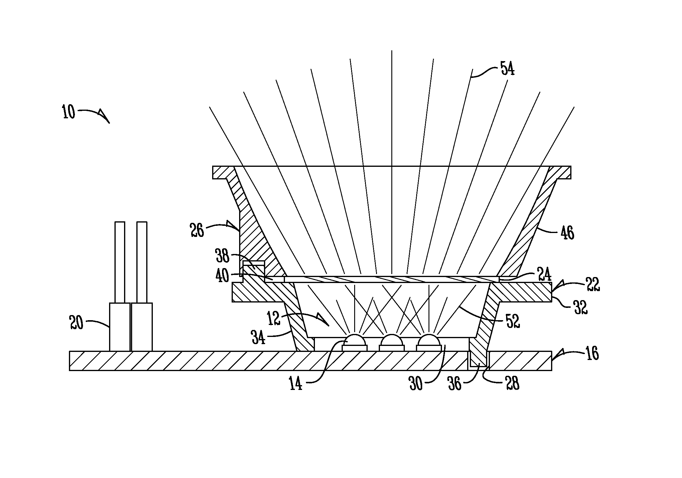
The present invention improves on the prior art by providing a light assembly that has several technical advantages. Firstly, it produces a beam of light that can provide beneficial effects to organisms. Secondly, it reduces the shadow effect caused by multiple LED lights placed together. Thirdly, it combines the beams of individual lights into a single beam with a specific direction and orientation. Fourthly, it is easy to hook up to a power source. Fifthly, it incorporates multiple lenses. These technical effects make the LED light assembly more efficient and effective for its intended purposes.

Problems solved by technology

In addition, LEDs have a much longer lifetime than either fluorescent or incandescent bulbs.
However, the cluster of LED lights used to create the beams of light can produce unwanted shadow effects.
The non-uniform beam can be deficient with regards to its intended purpose, which may be to provide physiological benefits to an organism to which the beam is intended to be directed.

Method used


Image

  • LED light
  • LED light
  • LED light

Examples


Embodiment Construction

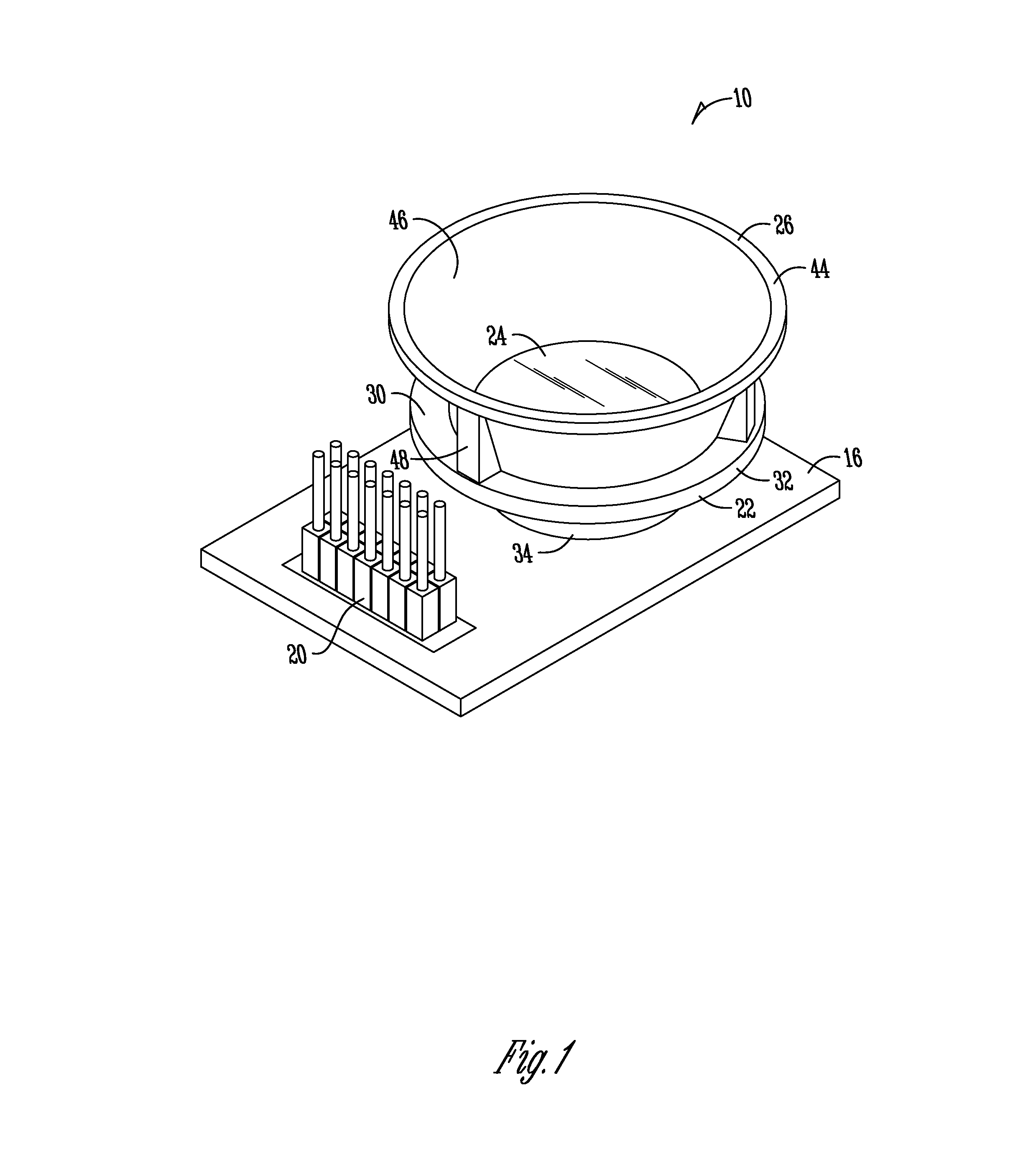
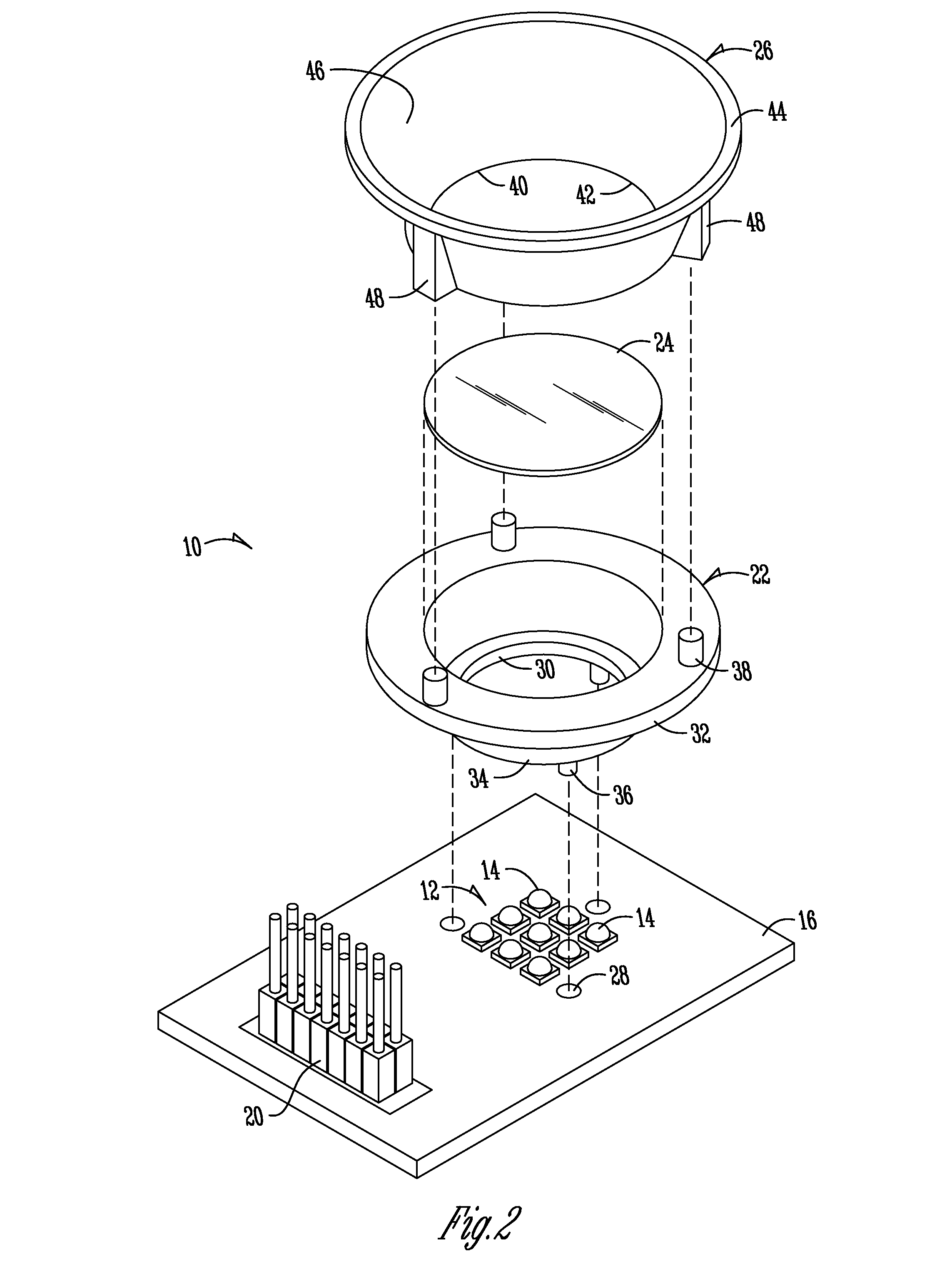
[0025]FIG. 1 is a perspective view of an LED light assembly 10 according to an embodiment of the invention. The light assembly 10 as shown and described can be used with aquariums or other environments, including both faux environments and real environments, such as an outside area. The assembly 10 according to the embodiments of the present invention provides numerous benefits over previous light assemblies. For example, as will be understood, the light assembly 10 includes a cluster of LED lights 12 that will provide a light source for a location in the aquarium or other environment that captures the light emitted from substantially all of the lights to produce a uniform beam of light. The configurations of the embodiments of the invention will reduce a shadowing effect caused by the use of multiple LED lights 14 being oriented towards a certain direction or end point or end point area. Thus, the invention provides for an assembly that will have a more uniform light beam 54 obtain...


PUM


Abstract

The present invention is directed towards a light assembly, such as an LED light assembly. A cluster of light beams positioned on a substrate and connected to a power source. The light beams produced by the cluster of LED lights are captured in a mixing chamber and passed through an optical diffusing member. The plurality of light beams will be combined by the combination of the mixing chamber and optical diffuser such that a more uniformed beam is produced. The uniformed beam is then passed through a lens member to be oriented or directed towards the intended location or use of the light beam produced by the light assembly.

Description

FIELD OF THE INVENTION[0001]The present invention relates generally to lighting systems. More particularly, but not exclusively, the invention relates to an LED light assembly that reduces shadowing effect caused by a cluster of lights to increase physiological benefits of the light.BACKGROUND OF THE INVENTION[0002]Light emitting diode (LED) lights, and more particularly, groups of LED lights, are currently used to illuminate a variety of areas. The lights are placed in clusters to provide a specifically oriented ray of light, as with a flashlight, or they are added to strips for illuminating a larger, more generalized area. Although a number of LEDs are needed to produce enough light to illuminate a desired area, LEDs do not require as much energy as standard lighting, and are more efficient than incandescent bulbs. In addition, LEDs have a much longer lifetime than either fluorescent or incandescent bulbs. The lifetime is generally three to four times longer than fluorescent tubes...

Claims


Application Information

Patent Timeline
IPC IPC(8): F21V13/02
CPCF21V13/02F21V7/00F21V23/005F21K9/62F21Y2105/10F21Y2115/10
Inventor CLOUGH, CHRISTIAN JAMES
Owner C2 DEV
Learn More