Micro-invasive device

a micro-invasive and device technology, applied in the field of medical devices, can solve the problems of difficult to determine if pre-palpable breast abnormalities are malignant, difficult to determine if they are malignant, and expensive,

Inactive Publication Date: 2008-03-13
STRYKER PUERTO RICO LLC
View PDF10 Cites 97 Cited by
  • Summary
  • Abstract
  • Description
  • Claims
  • Application Information

AI Technical Summary

Benefits of technology

[0016] New apparatus and methods for removing breast tissue and / or other material from a human breast have been discovered. The present invention provides apparatus, for example, micro-invasive apparatus, to remove tissue or other material from a target area of a breast to provide one or more benefits, such as diagnostic benefits, therapeutic benefits and the like.

Problems solved by technology

The type of biopsy utilized depends in large part on circumstances present with respect to the patient and no single procedure is ideal for all cases.
However, definitive tissue characterization still requires obtaining adequate tissue samples to characterize the histology of the organ or lesion.
However, it is often difficult to determine if pre-palpable breast abnormalities are malignant, as some benign lesions have mammographic features which mimic malignant lesions and some malignant lesions have mammographic features which mimic benign lesions.
Thus, mammography has its limitations.
They can be disfiguring, expensive and are imperfect open surgical biopsies also carry a small mortality risk (due to the risks of anesthesia) and a moderate morbidity rate (including bleeding, infection, and fracture or migration of the localizing wire).
In cases where multiple lesions are present in the breast, a surgeon is reluctant to biopsy each lesion due to the large tissue mass that must be extracted with each lesion.
The most convenient lesion may be taken which most often results in an incomplete diagnosis.
One drawback to the manual technique is that it requires a great deal of manual dexterity and motor coordination, along with the use of both hands, to advance the stylet while maintaining the position of the cannula and then to maintain the position of the stylet while advancing the cannula.
Another drawback is that the cannula is advanced relatively slowly, resulting in an extremely poor cutting action and allowing the surrounding tissue an opportunity to collapse, thus making no use of the stored kinetic energy in the material being severed.
Further disadvantages are encountered when the tissue volume to be sampled contains areas of higher density than that of surrounding tissue, such as areas of calcification commonly associated with certain types of cancerous growths.
A manually inserted sampling device is often incapable of penetrating the denser area of tissue which merely deflects the course of the cannula / stylet structure around the dense area and into the more compliant surrounding tissue.
However, there are limiting factors with image-guided breast biopsies.
Conventional, manually operated two-step devices are awkward to manipulate, and the tissue samples obtained thereby are often unsatisfactory.
Also, since the stylet is not removable proximally from within the handle, the entire instrument must be withdrawn to obtain access to the sample.
This instrument, however, also has its drawbacks.
First, the reusable handpiece is very large, heavy, cumbersome, and expensive.
Such “cocking” of the gun requires considerable force and the gun must be cocked for each biopsy cut.
When actuated, the springs provided in the gun accelerate the needles until a mechanical stop position is reached which can create a loud snapping noise and jerking motion which is a problem both to the physician and the patient.
A further drawback is encountered in automatically activating both the stylet and the cannula, as opposed to activating the stylet manually, in that the rapid speed at which the cannula follows the stylet into the tissue does not allow much tissue to collapse into the specimen notch, limiting the size of the sample.

Method used


Image

  • Micro-invasive device
  • Micro-invasive device
  • Micro-invasive device

Examples


Embodiment Construction

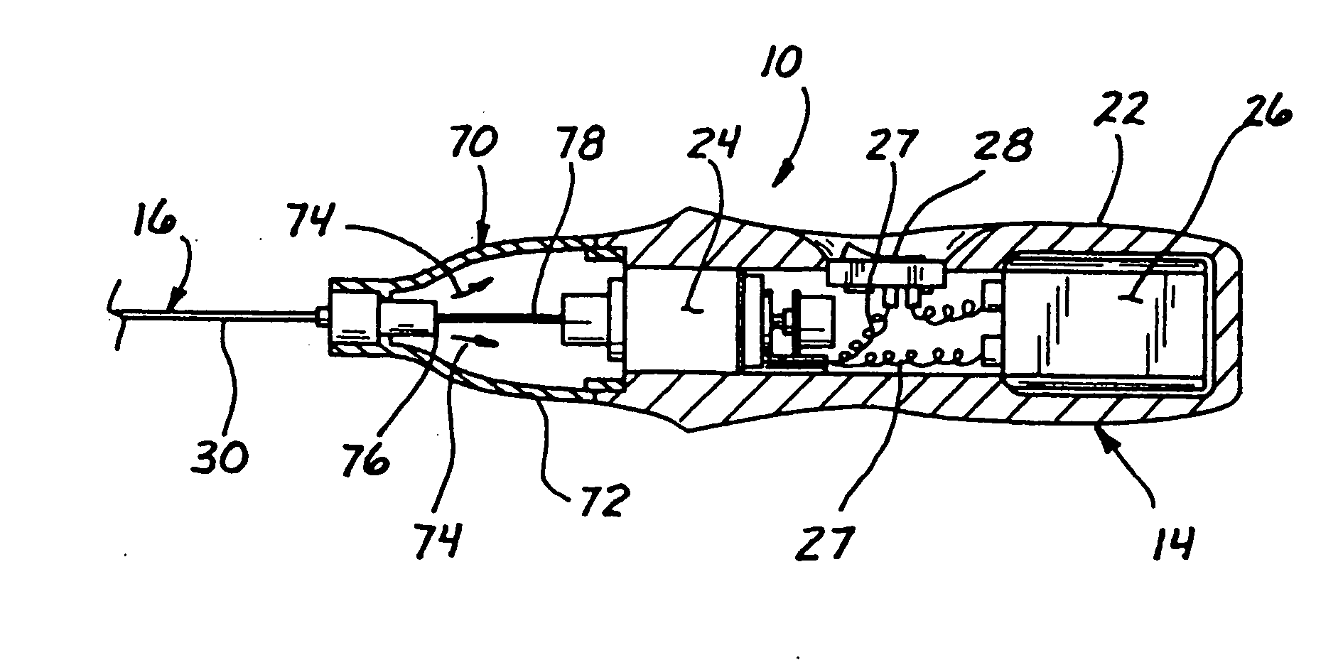
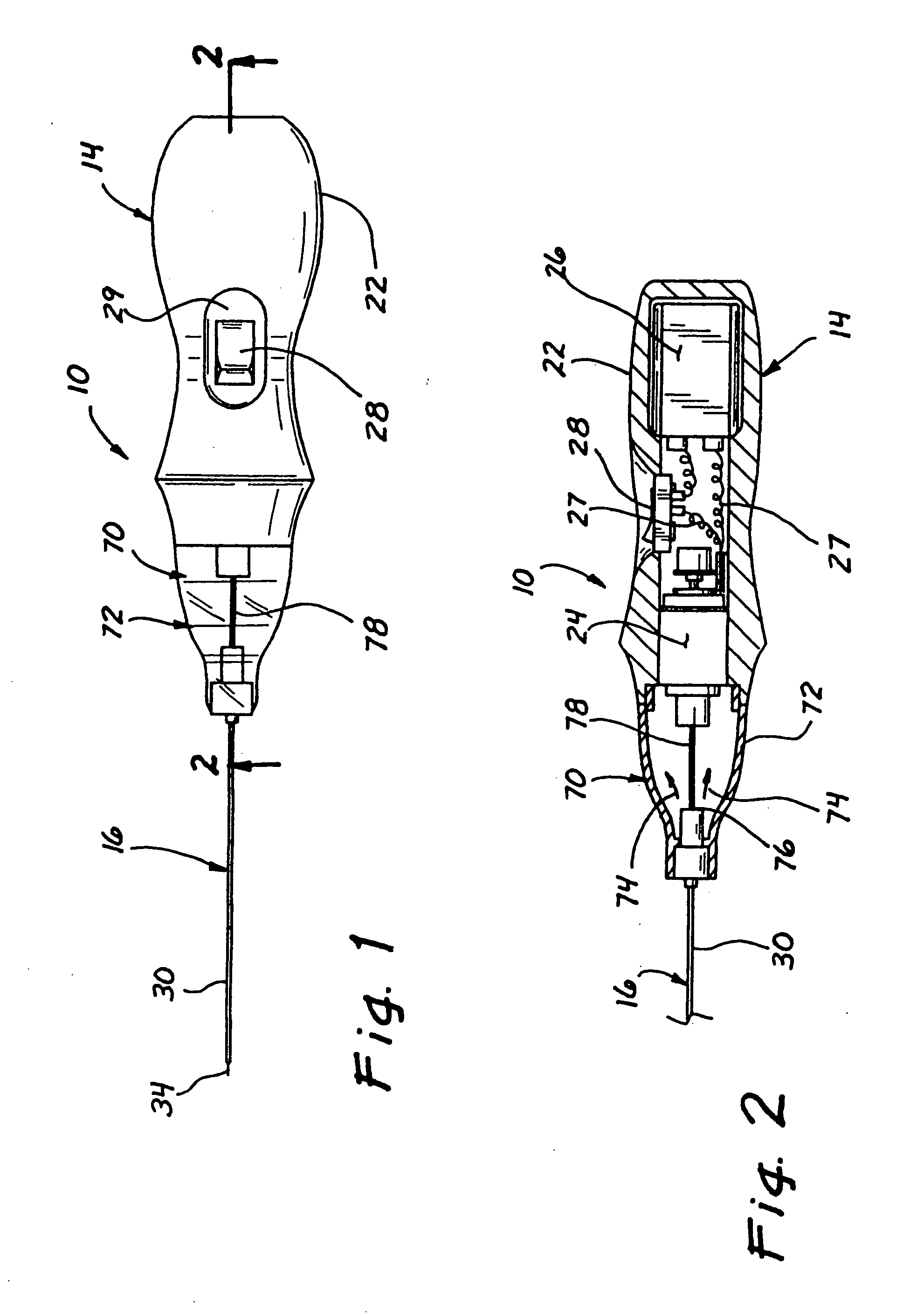
[0043] Turning now to FIGS. 1 and 2, a micro-invasive tissue removal apparatus for removing tissue or other material from a breast, in accordance with the present invention is shown generally at 10. The apparatus 10 generally comprises a handpiece 14 and a tissue removal mechanism 16 to be described in detail hereinafter.

[0044] The handpiece 14 is preferably sized and contoured to fit comfortably within a palm of a surgeon, and includes for example a molded plastic housing 22. As shown in FIG. 2, the housing 22 of the handpiece 14 encloses a small motor 24 and a power supply, for example a 9 volt battery 26 for driving the tissue removal mechanism 16. Suitable electrical connectors 27 are provided. For convenient, one handed operation, an ON / OFF switch 28 is preferably provided on a recessed, lateral portion 29 of the housing 22.

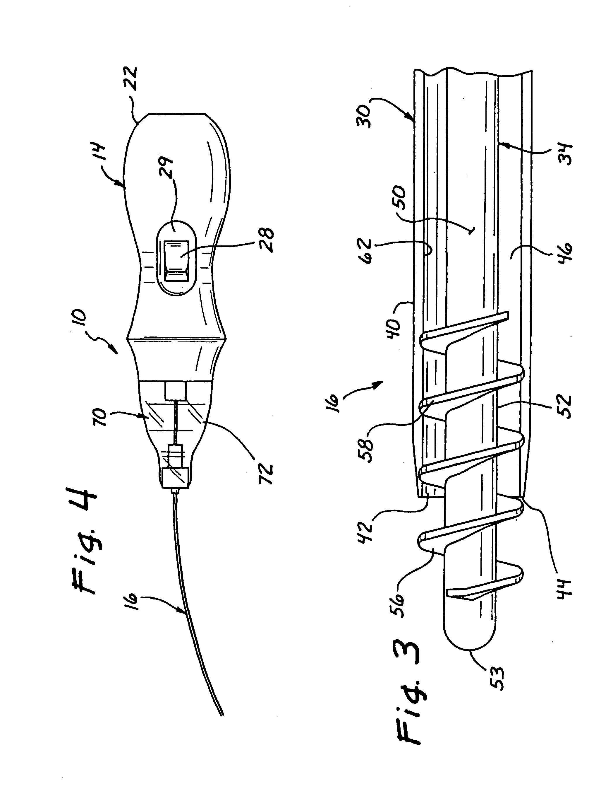
[0045] Turning now as well to FIG. 3, the tissue removal mechanism 16 generally includes a cannula 30 and a rotatable element 34 disposed therein. As show...


PUM


Abstract

An apparatus for removing tissue and/or other material from a patient, particularly a breast of a patient, is provided. The apparatus generally includes a handpiece and a tissue removal mechanism connected thereto. The tissue removal mechanism includes a cannula having an open distal tip and an outer diameter of less than about 5 mm, or less than about 2 mm. The mechanism further includes a rotatable element having a distal portion with helical threading. The distal portion of the rotatable element extends beyond the open distal tip of the cannula in order to allow tissue to prolapse between turns of the helical threading. The apparatus is designed to draw soft tissue into the cannula upon rotation of the rotatable element and without the need for supplemental sources of aspiration.

Description

RELATED APPLICATION [0001] This application is a continuation of application Ser. No. 10 / 667,768, filed Sep. 22, 2003, which application is a continuation of Ser. No. 10 / 093,765, filed Mar. 8, 2002, which claims the benefit of U.S. provisional application Ser. No. 60 / 278,128, filed Mar. 23, 2001 and Ser. No. 60 / 281,848, filed Apr. 5, 2001 and Ser. No. 60 / 305,178 filed Jul. 13, 2001 and Ser. No. 60 / 322,909, filed Sep. 17, 2001 and Ser. No. 60 / 342,436, filed Dec. 21, 2001, the disclosure of each of which is incorporated in its entirety herein by reference.FIELD OF THE INVENTION [0002] The present invention relates generally to medical devices, and, more particularly, to micro-invasive devices and methods for removing breast tissue for biopsy and treatment. BACKGROUND OF THE INVENTION [0003] The medical industry is constantly evolving through the adaptation of improved pharmaceutical, biotechnology, and medical device products and procedures. Techniques and technologies are being devel...

Claims


Application Information

Patent Timeline
Patent Type & Authority Applications(United States)
IPC IPC(8): A61B10/02A61B10/00A61B17/00A61B17/22A61B17/32
CPCA61B10/0096A61B10/0266A61B17/32002A61B2017/008A61B2017/00261A61B2017/00685A61B2017/00734A61B2010/0225
Inventor PFLUEGER, D. RUSSELL
Owner STRYKER PUERTO RICO LLC
Why Eureka
Try Eureka