Multi-stream microchannel device

a microchannel device and multi-stream technology, applied in lighting and heating apparatus, physical/chemical process catalysts, bulk chemical production, etc., can solve the problems of insufficient design of mct heat exchangers, and inability to meet the needs of industrial production

Inactive Publication Date: 2006-03-21
VELOCYS CORPORATION
View PDF96 Cites 90 Cited by
  • Summary
  • Abstract
  • Description
  • Claims
  • Application Information

AI Technical Summary

Benefits of technology

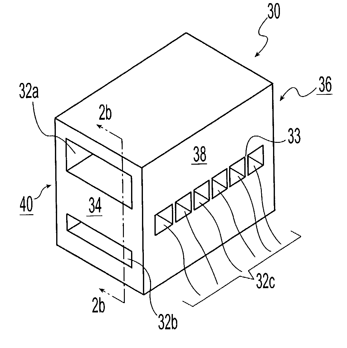
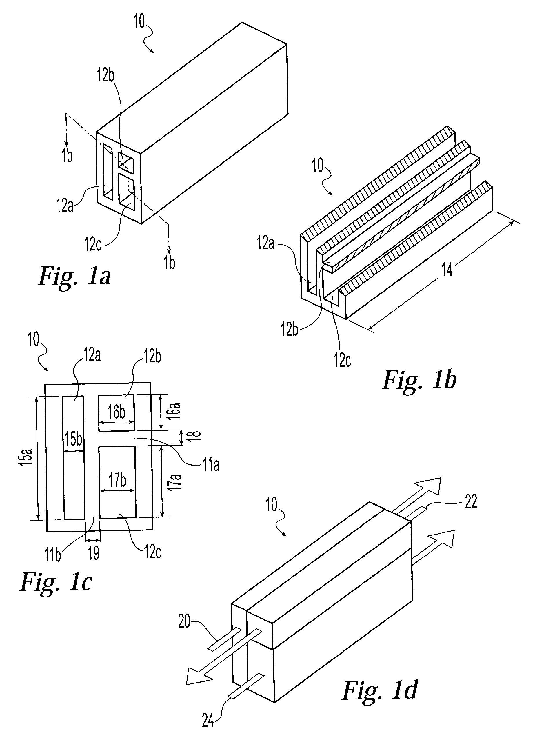
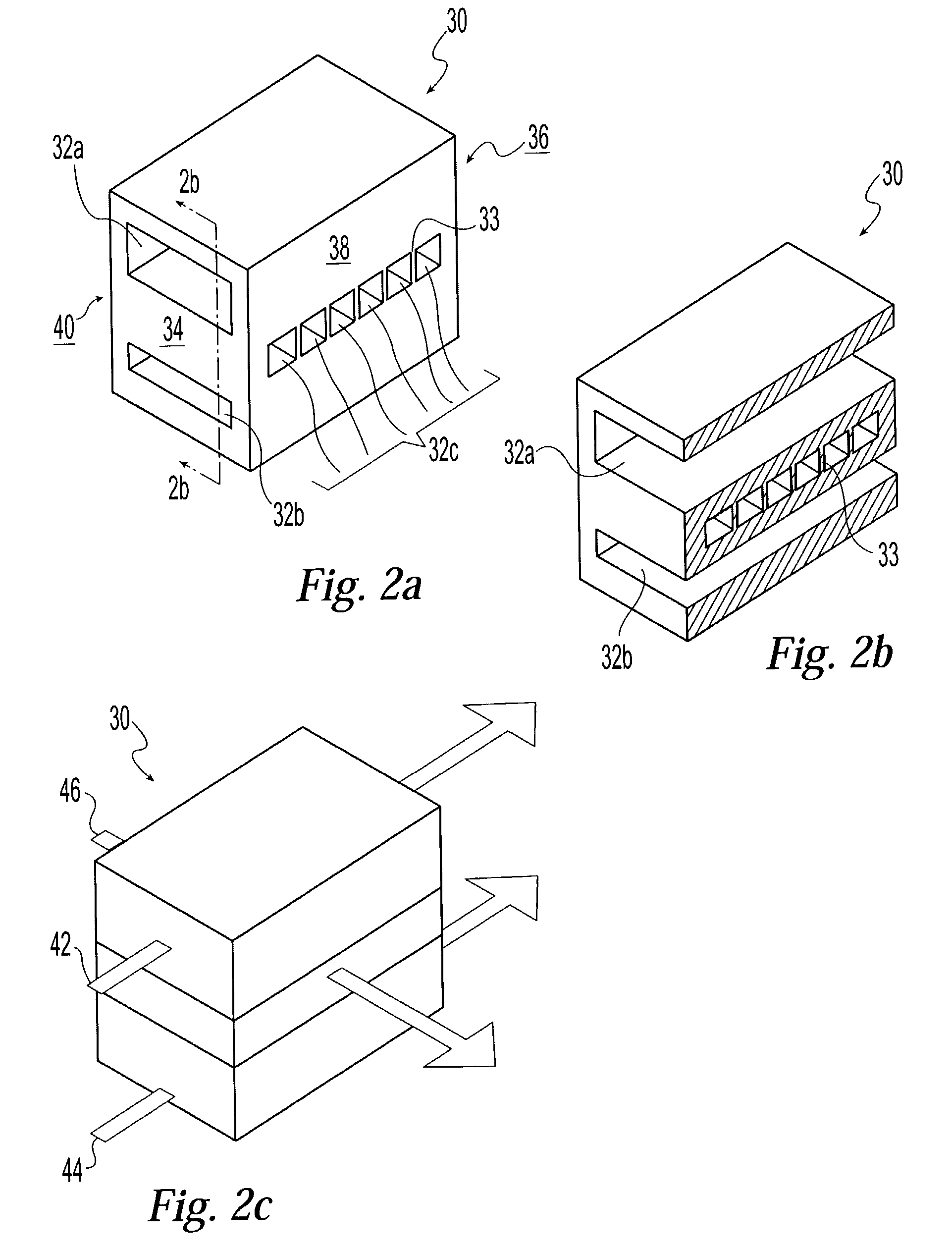
[0012]The present invention is a process and device for exchanging heat energy between three or more streams in an MCT heat exchanger, integrating the MCT heat exchanger with an MCT reactor to form an integrated MCT processing unit, combining a plurality of integrated MCT processing units into an integrated MCT processing system, and finally combining a plurality of integrated MCT systems into an MCT processing stack to provide the benefits of large-scale operation. Particularly, the MCT heat exchange process and device enables flexible heat transfer between multiple streams and total heat transfer rates of about 1 Watt (W) or more per core unit volume (cubic centimeters (cc)) (W / cc), pressure drop on the order of about 0.25 psi per in. or less, stream Reynolds Numbers in the transition or laminar zones, and interstream planar heat transfer percents of greater than about 30 percent. In some embodiments, the integrated MCT heat exchanger and MCT reactor exhibits a monotonically increasing temperature profile and, thus, thermal stresses are minimized.

Problems solved by technology

There are problems, however, even with existing MCT heat exchangers.
For example, MCT heat exchangers have not been designed which can process more than two separate streams in a single integral device.
Even multiple two-stream MCT heat exchangers, however, allow significantly more heat transfer to the ambient and the necessary stream transfer piping can cause higher pressure drops to redistribute flows or dead zones and eddies which can cause extended residence times. These extended residence times can cause fouling, corrosion, erosion, decomposition, formation of undesirable byproducts, and, for example, coke can be deposited when processing carbon-containing streams at elevated temperatures.
Thus, owing to having a large number of small MCT heat exchangers in close proximity and the close proximity of one channel to another, manifolding the streams entering and exiting an MCT heat exchanger (or any MCT device) becomes a problem.
When manifolding multiple streams in MCT devices, the design problem becomes even greater than designing a two-stream manifold.
There remain, however, special problems involving MCT reactors and the need for heat transfer.
For example, thermal stresses pose significant problems.
Thus, temperature differentials that could be easily tolerated by a conventional device of greater dimensions can produce unacceptable thermal stresses in an MCT device which is smaller and thus experiences a much higher temperature gradient.
Illustratively, an MCT reactor that is overly constrained geometrically either by multiple integral heat exchangers or integrally-combined multiple integral MCT heat exchanger / reactor units can be subjected to potentially destructive thermal stresses.
As a result, as with multiple two-stream MCT heat exchangers, there can be significant heat loss between multiple units to the ambient and through associated piping or tubing.
As noted herein above, such piping connections can become sites for fouling and coke-formation problems.
Alternatively, more expensive metals that can tolerate the thermal stresses or inexpensive throwaway devices must be employed.
In addition, the goal of combining multiple heat exchanger / reactor devices to provide economically high total throughput has proved to be elusive.
However, serious problems would be encountered.”).

Method used


Image

  • Multi-stream microchannel device
  • Multi-stream microchannel device
  • Multi-stream microchannel device

Examples


example 1

[0175]Referring now to FIGS. 10–15, a heat exchanger was specifically designed to simulate a heat exchanger according to one embodiment of the present invention. The heat exchanger used five distinct fluids, denoted in FIGS. 10–15 as Fluids A, B, C, D, and E. Fluids C and D were split into two streams each with each stream flowing through separate microchannels; fluids A, B, and E each flowed through separate microchannels (as Streams A, B, and E, respectively), making a total of seven microchannels in the heat exchanger. As shown in FIG. 10, Fluid C flowed through two microchannels as Stream C1 and Stream C2. Similarly, Fluid D flowed through two microchannels as Stream D1 and D2. The experimental results show the performance of the heat exchanger and the results as compared to numerical simulations from a computer program.

[0176]Referring again to FIG. 10, the heat exchanger consisted of seven rectangular microchannels, each ten inches (in.) long. The height of each microchannel wh...


PUM

PropertyMeasurementUnit
heightaaaaaaaaaa
heightaaaaaaaaaa
heightaaaaaaaaaa

Abstract

The invention is a process and device for exchanging heat energy between three or more streams in a microchannel heat exchanger which can be integrated with a microchannel reactor to form an integrated microchannel processing unit. The invention enables the combining of a plurality of integrated microchannel devices to provide the benefits of large-scale operation. In particular, the microchannel heat exchanger of the present invention enables flexible heat transfer between multiple streams and total heat transfer rates of about 1 Watt or more per core unit volume expressed as W / cc.

Description

CROSS-REFERENCE TO RELATED APPLICATIONS[0001]The present application is related to the following commonly-assigned applications filed concurrently herewith on Aug. 15, 2002: “Integrated Combustion Reactors and Methods of Conducting Simultaneous Endothermic and Exothermic Reactions”, now U.S. patent application Ser. No. 10 / 222,196 (U.S. Pub. No. US 2004 / 0033455 A1) and “Process for Cooling a Product in a Heat Exchanger Employing Microchannels for the Flow of Refrigerant and Product”, now U.S. Pat. No. 6,622,519. which applications are incorporated herein by reference.FIELD OF THE INVENTION[0002]This invention relates to microchannel devices and processes for multi-stream heat exchange and particularly to multi-stream heat exchange in combination with chemical reaction and more particularly to multi-stream heat exchange in combination with endothermic chemical reactions such as reforming and more particularly to endothermic reactions coupled with exothermic reactions such as combustio...

Claims


Application Information

Patent Timeline
Patent Type & Authority Patents(United States)
IPC IPC(8): C01B3/26B01J35/02B01J8/02F28D7/00B01J19/00B01J35/04C01B3/38F28D9/00F28F7/02
CPCB01J19/0093C01B3/384F16L41/02F28D7/0066F28D9/0093F28F7/02F28F3/12B01J35/04B01J2219/00869B01J2219/00891C01B2203/0233C01B2203/0822F28F2260/02C01B2203/0811Y02P20/52Y10T137/0318Y10T137/6579Y10T137/87249Y10T137/87153Y02P20/10
Inventor MATHIAS, JAMES ALLENCHADWELL, G. BRADLEYQIU, DONGMINGTONKOVICH, ANNA LEE Y.PERRY, STEVEN T.SCHMIDT, MATTHEW B.
Owner VELOCYS CORPORATION
Why Eureka
Try Eureka