
Hybrid vehicle drive control device

a hybrid vehicle and control device technology, applied in the direction of engine-driven generators, road transportation, transportation and packaging, etc., can solve the problems of difficulty in cancelling the first or second electric motor, and achieve the effect of preventing the influence of the reaction torque generated, and effectively preventing a variation of the vehicle drive for

Active Publication Date: 2015-01-15
TOYOTA JIDOSHA KK
View PDF33 Cites 6 Cited by
  • Summary
  • Abstract
  • Description
  • Claims
  • Application Information

AI Technical Summary

Benefits of technology

The present invention is a drive control system for a hybrid vehicle that is designed to prevent an influence of a reaction torque generated when the engine is stopped during running of the vehicle. This prevents a variation in the vehicle's drive force and a shock to the driver. The system uses two electric motors to generate torques in opposite directions, which work together to cancel out the reaction torque. This results in effective prevention of these negative effects. The system also allows for smooth stopping of the engine and reduction of the vehicle's drive force during braking. Additionally, the system can increase the torque capacity of the brakes to further improve safety and smoothness during braking.

Problems solved by technology

In the hybrid vehicle having a plurality of drive modes described above, however, it is difficult for the first or second electric motor to cancel the influence, on the drive force of the hybrid vehicle, of the reaction force generated to stop the rotary motion of the engine in the drive mode in which the drive force of the second electric motor cannot be transmitted directly to the output rotary member of the drive system, since the second electric motor is connected to the rotary element that is different from the output rotary member.

Method used


Image

  • Hybrid vehicle drive control device
  • Hybrid vehicle drive control device
  • Hybrid vehicle drive control device

Examples


first embodiment

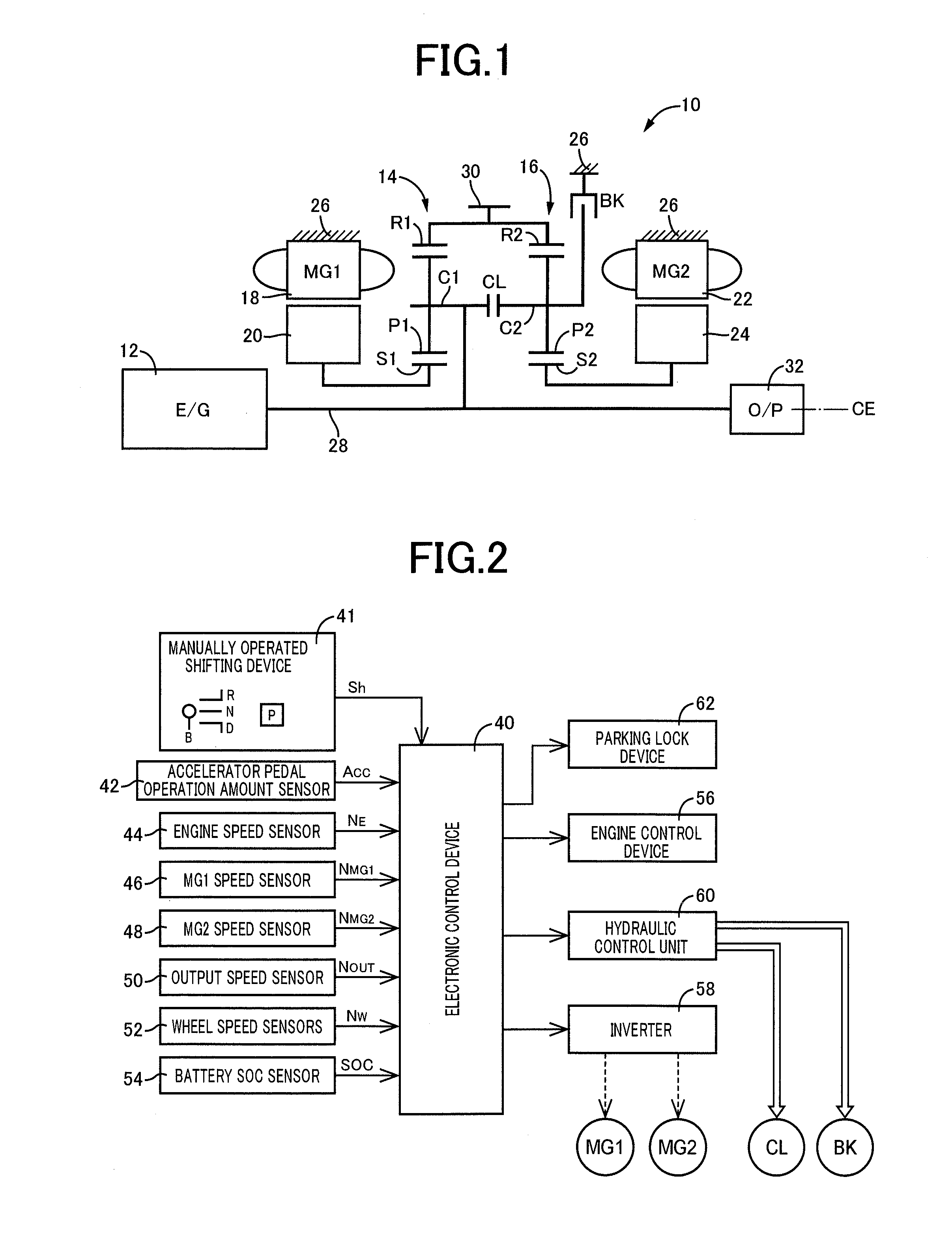
[0045]FIG. 1 is the schematic view for explaining an arrangement of a hybrid vehicle drive system 10 (hereinafter referred to simply as a “drive system 10”) to which the present invention is suitably applicable. As shown in FIG. 1, the drive system 10 according to the present embodiment is of a transversely installed type suitably used for an FF (front-engine front-drive) type vehicle, and is provided with a main vehicle drive power source in the form of an engine 12, a first electric motor MG1, a second electric motor MG2, a first differential mechanism in the form of a first planetary gear set 14, and a second differential mechanism in the form of a second planetary gear set 16, which are disposed on a common center axis CE. The drive system 10 is constructed substantially symmetrically with respect to the center axis CE. In FIG. 1, a lower half of the drive system 10 is not shown. This description applies to other embodiments which will be described.

[0046]The engine 12 is an inte...

second embodiment

[0093]FIGS. 14-19 are the schematic views for explaining arrangements of respective hybrid vehicle drive systems 100, 110, 120, 130, 140 and 150 according to other preferred modes of this invention used instead of the hybrid vehicle drive system 10 of the previous embodiment. The hybrid vehicle drive control device of the present invention is also applicable to drive systems such as the drive system 100 shown in FIG. 14 and the drive system 110 shown in FIG. 15, which have respective different arrangements of the first electric motor MG1, first planetary gear set 14, second electric motor MG2, second planetary gear set 16, clutch CL and brake BK in the direction of the center axis CE. The present hybrid vehicle drive control device is also applicable to drive systems such as the drive system 120 shown in FIG. 16, which have a one-way clutch OWC disposed between the carrier C2 of the second planetary gear set 16 and the stationary member in the form of the housing 26, in parallel wit...

third embodiment

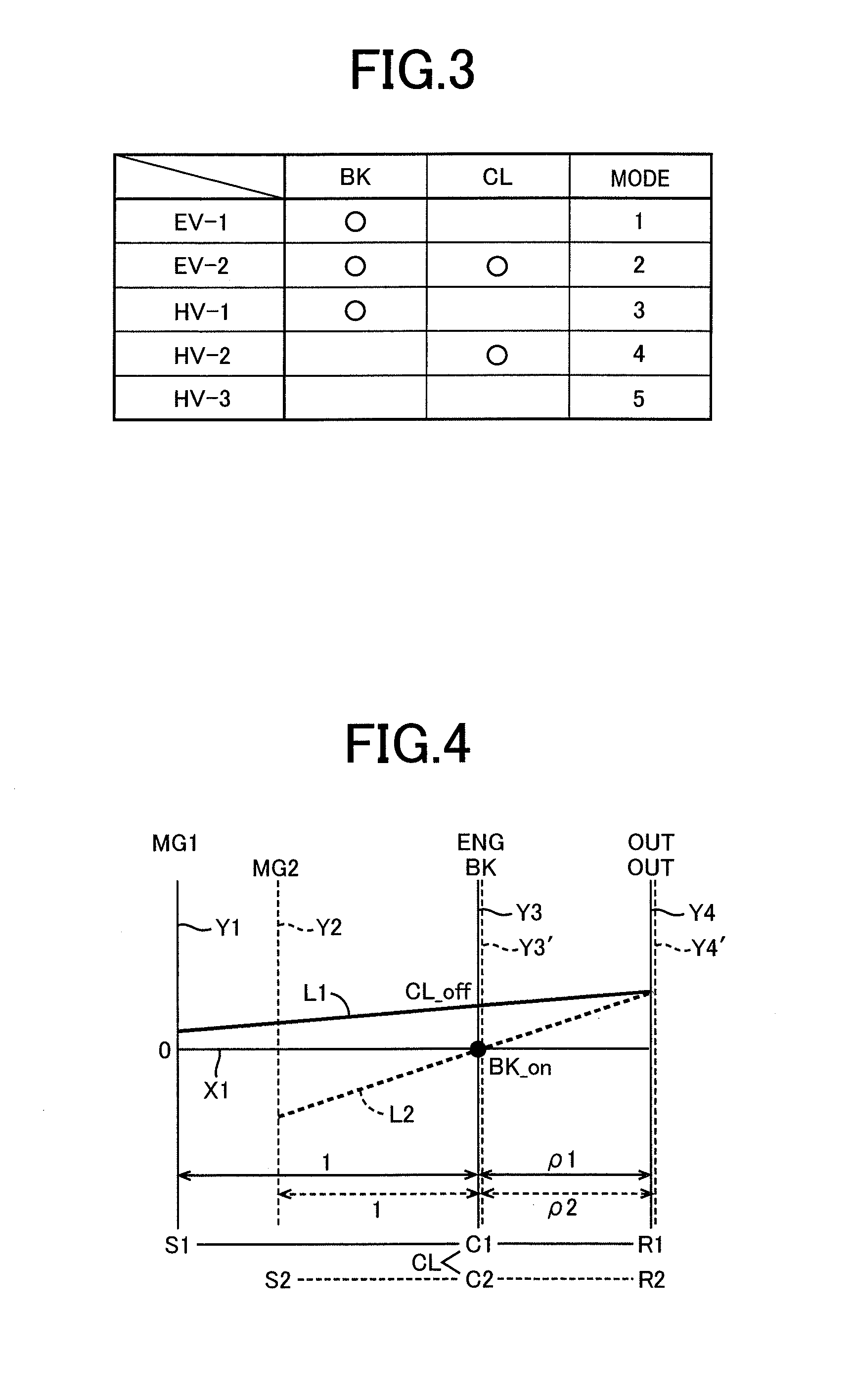
[0095]FIGS. 20-22 are the collinear charts for explaining arrangements and operations of respective hybrid vehicle drive systems 160, 170 and 180 according to other preferred modes of this invention in place of the drive system 10. In FIGS. 20-22, the relative rotating speeds of the sun gear S1, carrier C1 and ring gear R1 of the first planetary gear set 14 are represented by the solid line L1, while the relative rotating speeds of the sun gear S2, carrier C2 and ring gear R2 of the second planetary gear set 16 are represented by the broken line L2, as in FIGS. 4-7. In the drive system 160 for the hybrid vehicle, the sun gear S1, carrier C1 and ring gear R1 of the first planetary gear set 14 are respectively connected to the first electric motor MG1, engine 12 and second electric motor MG2, while the sun gear S2, carrier C2 and ring gear R2 of the second planetary gear set 16 are respectively connected to the second electric motor MG2 and output gear 30, and to the housing 26 throug...


PUM


Abstract

A drive control device for a hybrid vehicle is provided with a differential device including four rotary elements; and an engine, first and second electric motors and an output rotary member which are respectively connected to the four rotary elements. One of the four rotary elements is constituted by a rotary component of a first differential mechanism and a rotary component of a second differential mechanism selectively connected through a clutch, and one of the rotary components is selectively fixed to a stationary member through a brake. The drive control device comprises: an engine stop control portion configured to control the first and second electric motors so as to generate torques in respective opposite directions when the engine is required to be stopped during running of the hybrid vehicle in an engine drive mode in which the clutch is placed in an engaged state, the engine stop control portion reversing the directions of the torques generated by the first and second electric motors while the hybrid vehicle is in a coasting run, with respect to those generated while the hybrid vehicle is in a positive driving run.

Description

TECHNICAL FIELD[0001]The present invention relates to an improvement of a drive control device for a hybrid vehicle.BACKGROUND ART[0002]There is known a hybrid vehicle which is provided with a differential mechanism having a first rotary element connected to a first electric motor, a second rotary element connected to an engine, and a third rotary element connected to an output rotary member and a second electric motor, and a crankshaft locking device for inhibiting a rotary motion of a crankshaft of the engine, and which can run in an electric drive mode in which the first and second electric motors both are operated as a vehicle drive power source.PRIOR ART DOCUMENTPatent Document[0003]Patent Document 1: JP-2008-265600 A1SUMMARY OF THE INVENTIONObject Achieved by the Invention[0004]In the above-described hybrid vehicle which is provided with the second electric motor a drive force of which can be transmitted directly to an output shaft or an output rotary member of a drive system,...

Claims


Application Information

Patent Timeline
Patent Type & Authority Applications(United States)
IPC IPC(8): B60W20/00B60K17/02B60K6/445B60K6/26B60K6/442B60L50/16
CPCY10S903/915B60W20/40B60K17/02B60K6/445B60K6/26B60K6/442B60W10/06B60W10/08B60W20/00B60W2510/06B60W2520/00Y02T10/62B60K6/387B60K2006/381B60W30/18072B60W2710/083Y02T10/72Y02T10/60
Inventor MARUYAMA, TOMOYUKI
Owner TOYOTA JIDOSHA KK
Learn More