
LED Control Method and Apparatus

a technology of led control and control method, applied in the direction of electric light circuit arrangement, electrical apparatus, electroluminescent light source, etc., can solve the problems of requiring more precise, power consumption and overall power consumption of led power supply is merely 1 to 3, and achieves stably and reliably the effect of high power efficiency of led control units

Inactive Publication Date: 2015-01-15
ZHANG ZHIJUN
View PDF2 Cites 13 Cited by
  • Summary
  • Abstract
  • Description
  • Claims
  • Application Information

AI Technical Summary

Benefits of technology

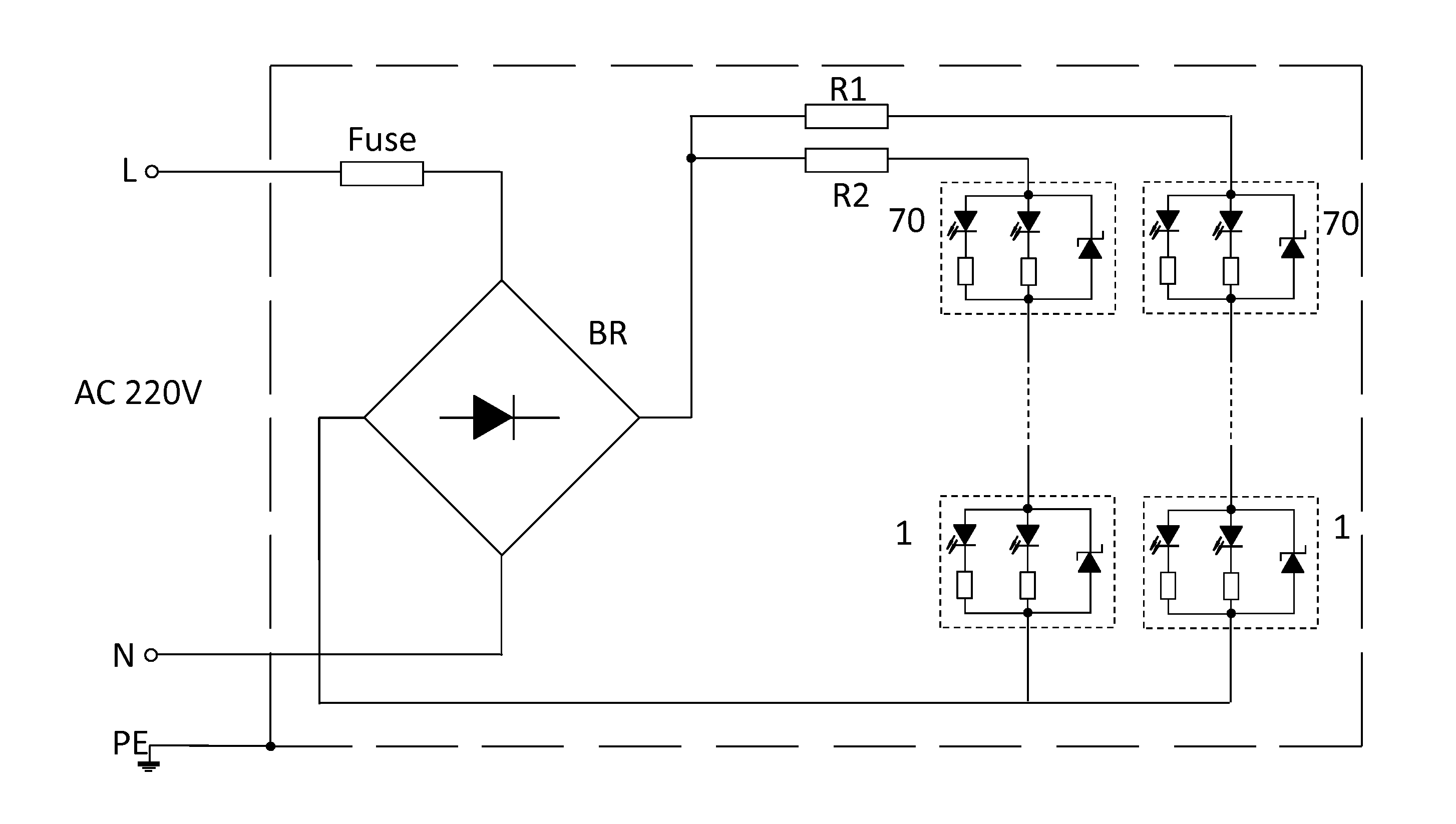
The present invention provides an LED control circuit that overcomes the dependence on voltage transformers and / or stable-volt, constant-current power supplies to provide LED loads the ideal working condition. The LED control circuit achieves stable voltage and constant current, which allows LED loads to work with a higher power efficiency and provides more stable operation. The LED control circuit is stable, reliable, and works stably and reliably without generating any heat.

Problems solved by technology

However, LEDs powerful enough for room lighting require more precise current and heat management than compact fluorescent lamp sources of comparable output.
However, due to the reactive power loss and low efficiency of voltage transformers and power consumption of stable-voltage power supplies, the ratio between LED load power consumption and overall power consumption of LED power supply is merely 1 to 3.

Method used


Image

  • LED Control Method and Apparatus
  • LED Control Method and Apparatus
  • LED Control Method and Apparatus

Examples


Embodiment Construction

[0015]The present invention is now described with reference to the drawings. The examples used herein are only for the purposes of illustration, they shall not be interpreted as to limit the scope of the claim of the invention.

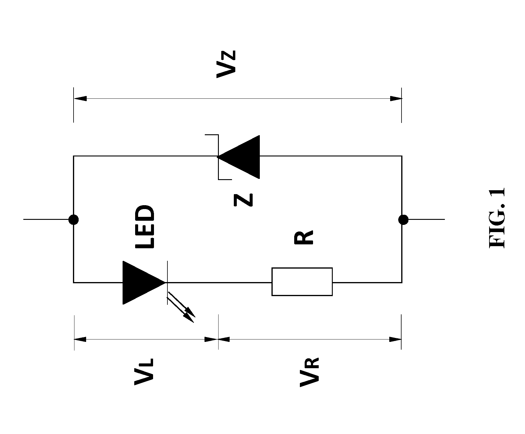
[0016]FIG. 1 illustrates an example of the LED control unit in its simplest form. As the voltage over the zener diode (VZ) equals to the sum of the voltage over the LED (VL) and the voltage over the current-limiting resistor (VR),

VZ=VLVR

VZ must be bigger than VL. The zener diode is selected based on its forward voltage drop so as to closely approximate the desired working voltage of the LED. Because of the voltage-ampere characteristics of the zener diode, the LED control unit described herein is able to provide a consistent working current to the LED by stabilizing the voltage over the LED. Other element or circuit may be used in place of the zener diode as long as it provides a stabilized voltage closely approximating the desired working voltage of the LED ...


PUM


Abstract

An LED control circuit designed for providing stable voltage to LED loads, which is comprised of a bridge rectifier connected with the power supply, at least one LED branch circuit comprised of LED control units in series connection with a current-regulating element. Each LED control unit is comprised of a zener diode parallelly connected with LED working elements made of an LED and a serially connected current limiting resistor. The forward voltage drop of the zener diode closely approximates the desired working voltage of the LED loads, and thus each LED control unit plays the role of a voltage regulator. When voltage of an LED control unit is below the stabilized voltage of the zener diode, the brightness of LED is continuously adjustable. When an LED branch circuit is put under the control of a constant current control module, the current flowing through each LED can be stabilized.

Description

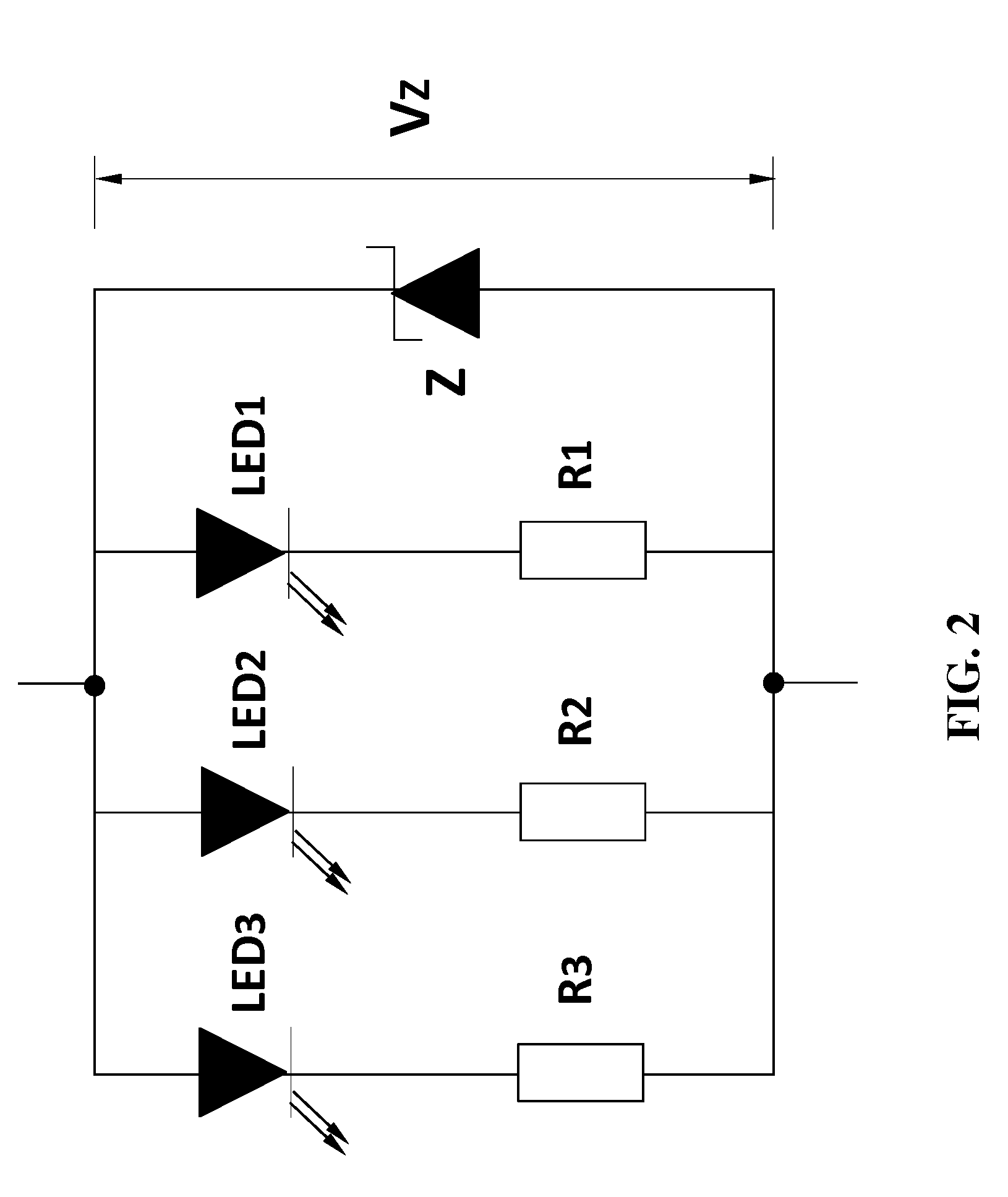
TECHNICAL FIELD[0001]The present invention relates to an LED control circuit designed for providing stable voltage to LED loads. The LED control circuit is comprised of a bridge rectifier connected with the power supply, one or more LED branch circuits in parallel connection, each branch circuit comprising one or more LED control units in series connection with a current-regulating element, either a current-limiting resistor or a constant current control module, which plays the role of controlling the current flowing through the LED branch circuit. Each LED control unit is comprised of a zener diode parallelly connected with one or more LED working elements. Each LED working element comprising an LED and a serially connected current limiting resistor, which plays the dual function of limiting the current flowing through the LED and providing a negative feedback upon the current.BACKGROUND OF THE INVENTION[0002]A light-emitting diode (LED) is a semiconductor light source. When an LED...

Claims


Application Information

Patent Timeline
Patent Type & Authority Applications(United States)
IPC IPC(8): H05B33/08H05B44/00
CPCH05B33/0809H05B33/0821H05B45/40Y02B20/30
Inventor ZHANG, ZHIJUN
Owner ZHANG ZHIJUN
Learn More