
Position detecting apparatus and driving system

a technology of position detection and driving system, which is applied in the direction of electronic commutators, process and machine control, instruments, etc., can solve the problems of reducing the accuracy of position detection and ensuring the accuracy of the amplitude of the signal

Active Publication Date: 2015-01-15
KK TOSHIBA
View PDF6 Cites 9 Cited by
  • Summary
  • Abstract
  • Description
  • Claims
  • Application Information

AI Technical Summary

Benefits of technology

The patent text describes a position detecting apparatus and a driving system that use a position measuring apparatus to detect the position of a movable body. The position detecting apparatus includes a sensor that outputs two position detection signals with different phases that vary with the same amplitude and the same period in response to a relative movement with respect to a scale. The apparatus includes amplifiers and a comparator to compare the signals and measure the phase angles of the signals. The apparatus also includes an AD converter to receive the signals and continuously read the value of the signal selected according to a selection signal. The apparatus includes a comparing part to compare the value of the digital signal with a reference value and output a control signal. The apparatus also includes an amplitude controlling part to control the amplification factors of the amplifiers in response to the control signal. The technical effect of this patent is to improve the accuracy of position detection in a driving system by compensating for changes in amplitude and offset with a closed loop control system.

Problems solved by technology

In such an arrangement, however, a deviation among the amplitude levels of the analog signals and a direct-current offset cause a decrease of the position detection precision.
However, only an open loop control, such as compensation based on early learning or a coefficient, is conducted, and the accuracy of the amplitude of the signal is not assured.

Method used


Image

  • Position detecting apparatus and driving system
  • Position detecting apparatus and driving system
  • Position detecting apparatus and driving system

Examples


first embodiment

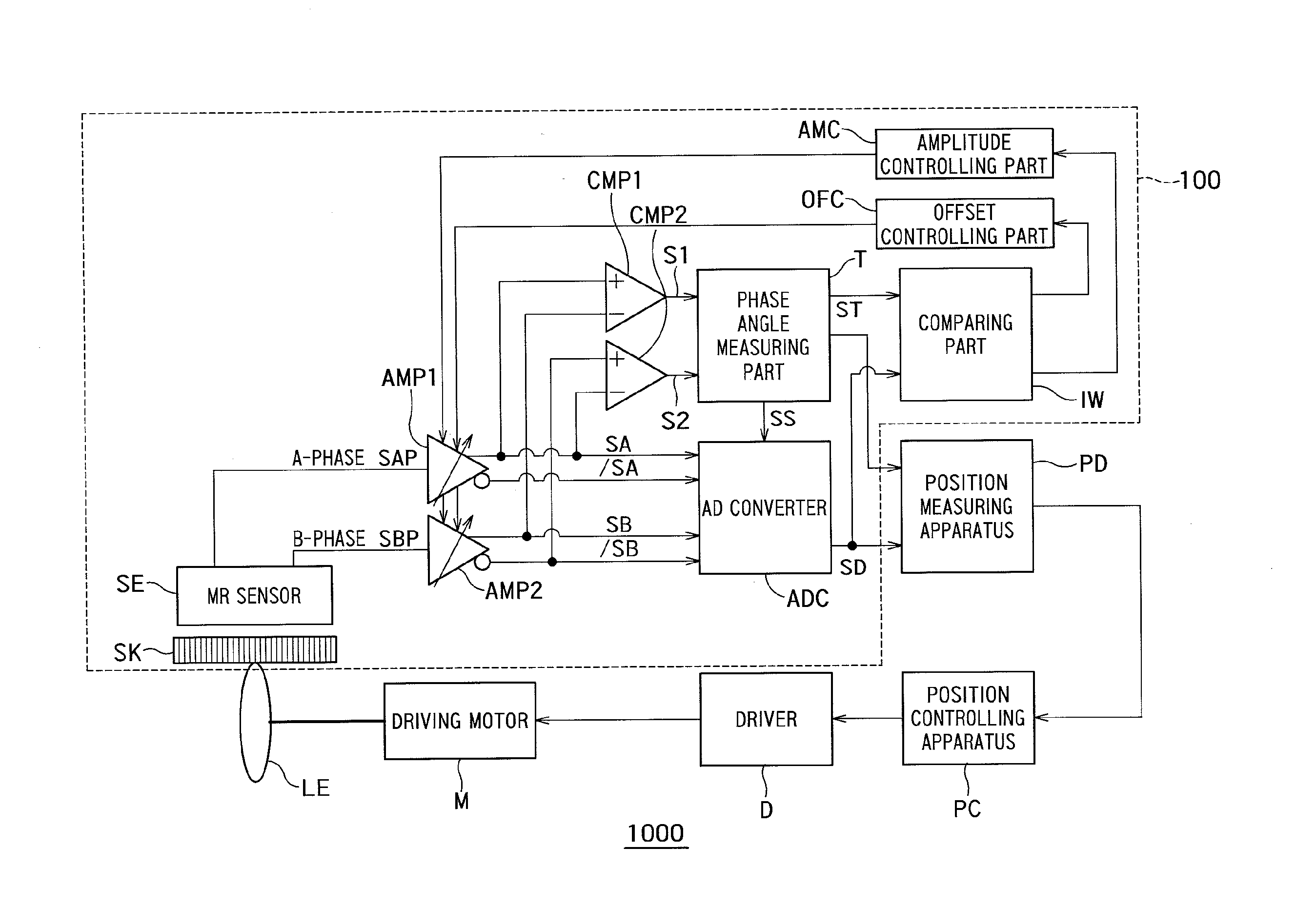
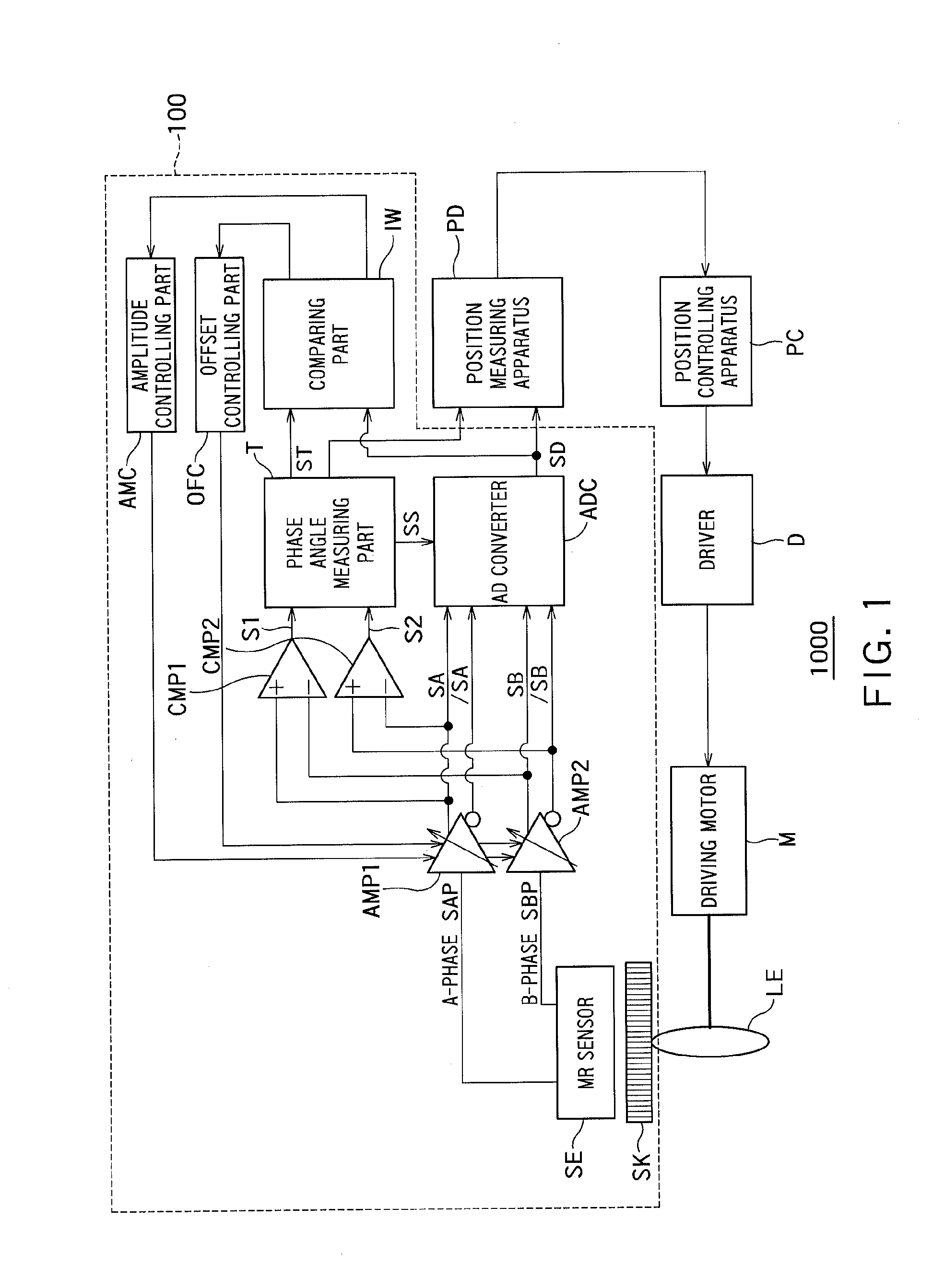
[0012]FIG. 1 is a diagram showing an example of a configuration of a driving system 1000 that incorporates a position detecting apparatus 100 according to a first embodiment.

[0013]As shown in FIG. 1, the driving system 1000 includes a movable body “LE”, a driving motor “M”, a position measuring apparatus “PD”, a position controlling apparatus “PC”, a driver “D”, and the position detecting apparatus 100.

[0014]In this embodiment, the movable body “LE” is a lens, for example.

[0015]When the driving motor “M” is driven, the driving motor “M” moves the movable body “LE”. The driving motor “M” is a linear motor, for example.

[0016]The driver “D” drives the driving motor “M”.

[0017]The position detecting apparatus 100 outputs a signal responsive to the position of the movable body “LE” (a phase angle measurement result and a digital signal described later).

[0018]The position measuring apparatus “PD” obtains the position of the movable body “LE” (position with respect to a reference position i...


PUM


Abstract

The position detecting apparatus includes a comparing part that compares the value of the digital signal output from the AD converter and a reference value that is based on a preset reference amplitude at the timings and outputs a control signal responsive to a result of the comparison. The position detecting apparatus includes an amplitude controlling part that controls amplification factors of the first amplifier and the second amplifier in such a manner that the value of the digital signal output from the AD converter comes closer to the reference value in response to the control signal output from the comparing part.

Description

CROSS-REFERENCE TO RELATED APPLICATION[0001]This application is based upon and claims the benefit of priority from the prior Japanese Patent Application No. 2013-146893, filed on Jul. 12, 2013, the entire contents of which are incorporated herein by reference.BACKGROUND[0002]1. Field[0003]Embodiments described herein relate generally to a position detecting apparatus and a driving system.[0004]2. Background Art[0005]As a means of position detection for a linear motor or the like, an arrangement is used in which a magnetic scale, an MR sensor (magnetic reluctance sensor) or the like operates in two phases. Such a position detecting arrangement incorporates a detector that uses the analog signal level of the MR sensor and means for counting the MR signal wave number to improve the resolution of the magnetic scale. In such an arrangement, however, a deviation among the amplitude levels of the analog signals and a direct-current offset cause a decrease of the position detection precisio...

Claims


Application Information

Patent Timeline
IPC IPC(8): G01B7/00H02P6/00G01D5/244
CPCH02P6/006G01B7/003G01D5/2448H02P6/16
Inventor ARIGA, HIROSHIINOUE, MASAHIRO
Owner KK TOSHIBA
Learn More