Portable wireless charging pad

Active Publication Date: 2015-01-15
ENERGOUS CORPORATION
View PDF5 Cites 266 Cited by
  • Summary
  • Abstract
  • Description
  • Claims
  • Application Information

AI Technical Summary

Benefits of technology

[0013]The disclosed embodiments provide wireless charging pads that may not require a power cord for connecting to a power supply. Thus, mobility and portability may greatly be enhanced in such pads

Problems solved by technology

Such an activity may be tedious and may represent a burden to users.
However, such an activity may render electronic devices inoperable during charging.
Nevertheless, such

Method used


Image

  • Portable wireless charging pad
  • Portable wireless charging pad
  • Portable wireless charging pad

Examples


Example

DETAILED DESCRIPTION OF THE DRAWINGS

Definitions

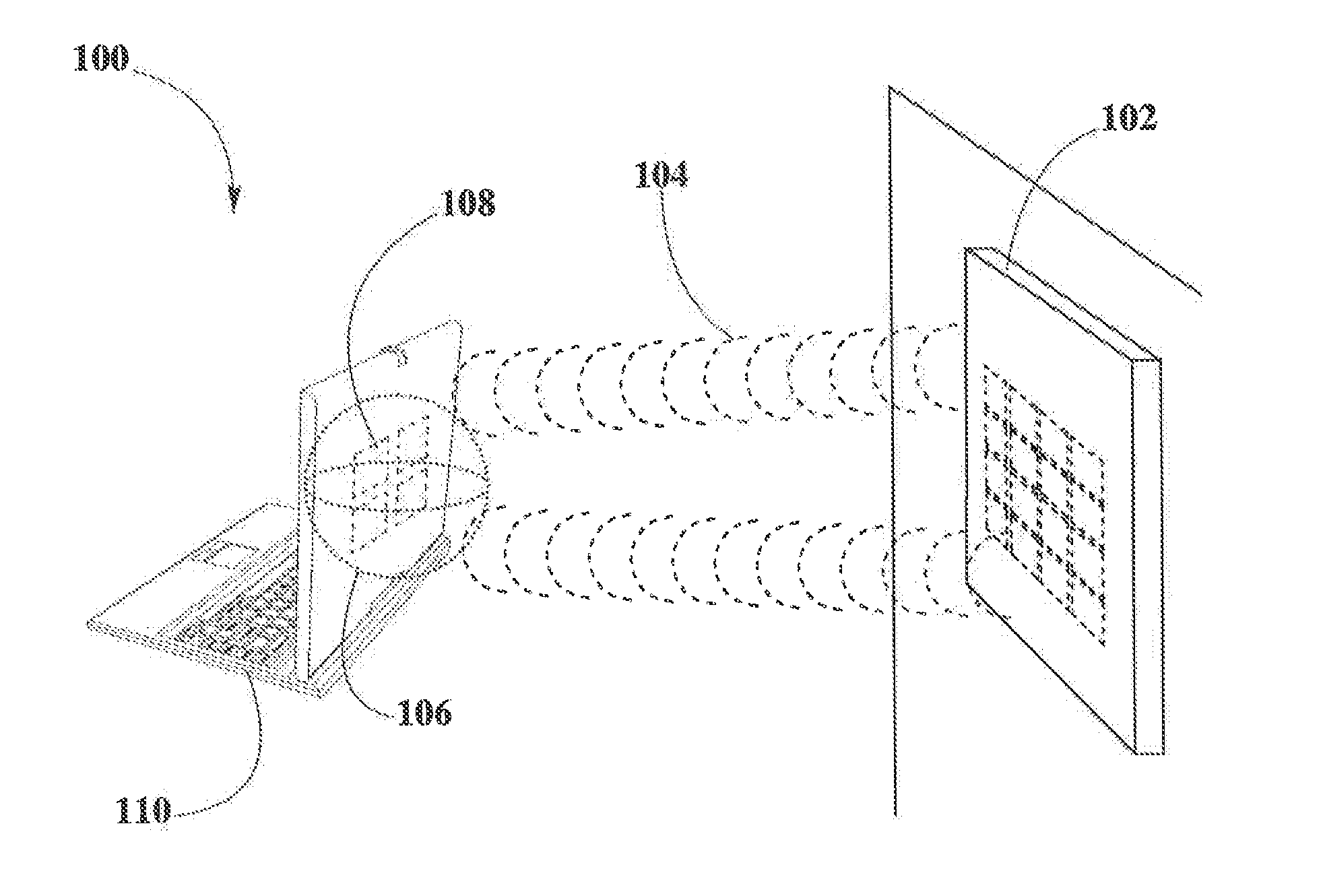
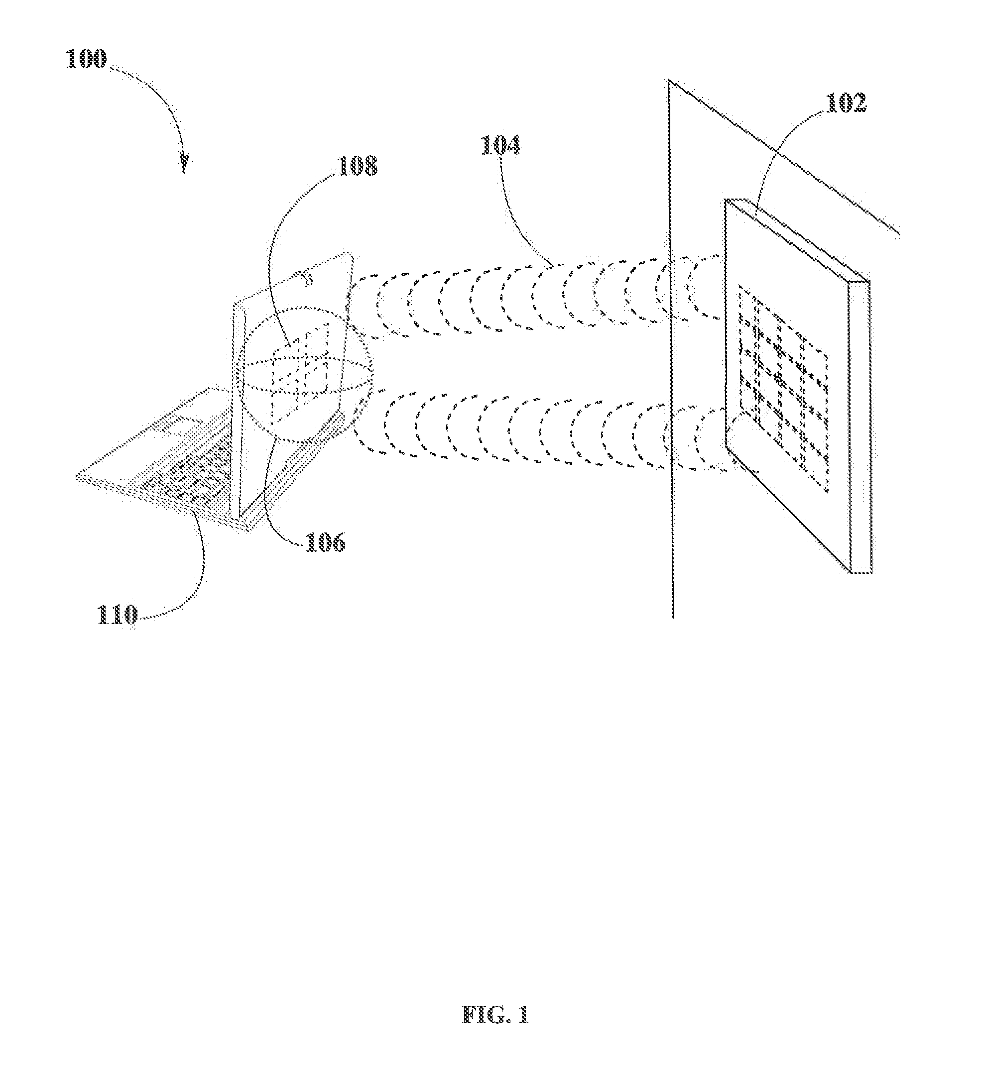
[0022]“Pocket-forming” may refer to generating two or more RF waves which converge in 3-d space, forming controlled constructive and destructive interference patterns.

[0023]“Pockets of energy” may refer to areas or regions of space where energy or power may accumulate in the form of constructive interference patterns of RF waves.

[0024]“Null-space” may refer to areas or regions of space where pockets of energy do not form because of destructive interference patterns of RF waves.

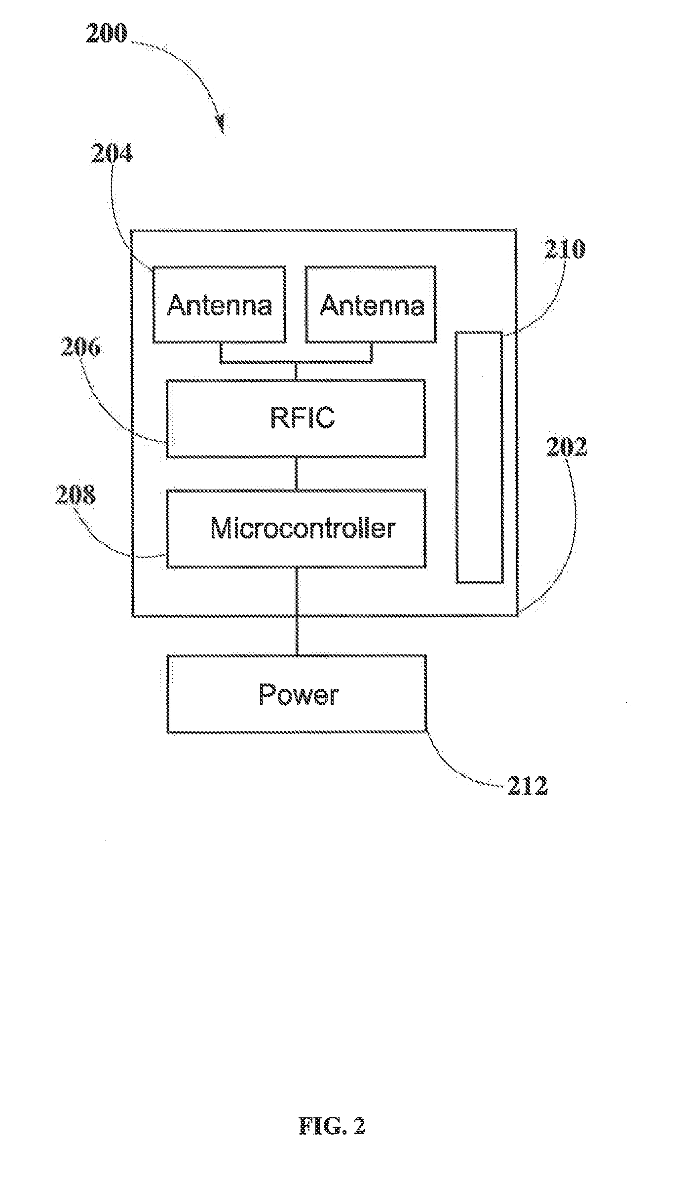
[0025]“Transmitter” may refer to a device, including a chip which may generate two or more RE signals, at least one RF signal being phase shifted and gain adjusted with respect to other RF signals, substantially all of which pass through one or more RE antenna such that focused RF signals are directed to a target.

[0026]“Receiver” may refer to a device which may include at least one antenna, at least one rectifying circuit and at least one power converter for power...


PUM


Abstract

The present disclosure provides a method and apparatus for improved wireless charging pads for charging and/or powering electronic devices. Such pads may not require a power chord for connecting to a main power supply, for example a wall outlet. In contrast, power may be delivered wireless to the foregoing pads through pocket-forming. A transmitter connected to a power source may deliver pockets of energy to the pads which through at least one embedded receiver may convert such pockets of energy to power. Lastly, the pads may power and/or charge electronic devices through suitable wireless power transmission techniques such as magnetic induction, electrodynamics induction or pocket-forming.

Description

CROSS-REFERENCES TO RELATED APPLICATIONS[0001]The present disclosure is related to U.S. Non-Provisional patent application Ser. No. 13 / 891,430 filed May 20, 2013, entitled “Methodology For Pocket-forming” and Ser. No. 13 / 925,469 filed Jun. 24, 2013, entitled “Methodology for Multiple Pocket-Forming” the entire contents of which are incorporated herein by these references.FIELD OF INVENTION[0002]The present disclosure relates to charging pads, and more particularly to portable wireless charging pads.BACKGROUND OF THE INVENTION[0003]Electronic devices such as laptop computers, smartphones, portable gaming devices, tablets and so forth may require power for performing their intended functions. This may require having to charge electronic equipment at least once a day, or in high-demand electronic devices more than once a day. Such an activity may be tedious and may represent a burden to users. For example, a user may be required to carry chargers in case his electronic equipment is lac...

Claims


Application Information

Patent Timeline
IPC IPC(8): H02J7/02
CPCH02J7/025H02J7/0042H02J50/10H02J50/20H02J50/80H02J50/90H02J50/402H02J7/04
Inventor LEABMAN, MICHAEL A.BREWER, GREGORY SCOTT
Owner ENERGOUS CORPORATION
Why Eureka
Try Eureka