Wireless charging device and method for controlling wireless charging

Inactive Publication Date: 2015-01-15
KK TOKAI RIKA DENKI SEISAKUSHO +1
View PDF32 Cites 15 Cited by
  • Summary
  • Abstract
  • Description
  • Claims
  • Application Information

AI Technical Summary

Benefits of technology

[0006]It is an object of the present invention to provide a wireless charging device and a method for

Problems solved by technology

Thus, when such a charging device is set in a vehicle, radio wave interference may occur between the wireless charging system and the electronic key system.
More specifically, when the charging device is used inside the vehicle, t

Method used


Image

  • Wireless charging device and method for controlling wireless charging
  • Wireless charging device and method for controlling wireless charging
  • Wireless charging device and method for controlling wireless charging

Examples


first embodiment

[0019]A wireless charging device according to a first embodiment of the present invention will now be discussed with reference to FIGS. 1 to 4.

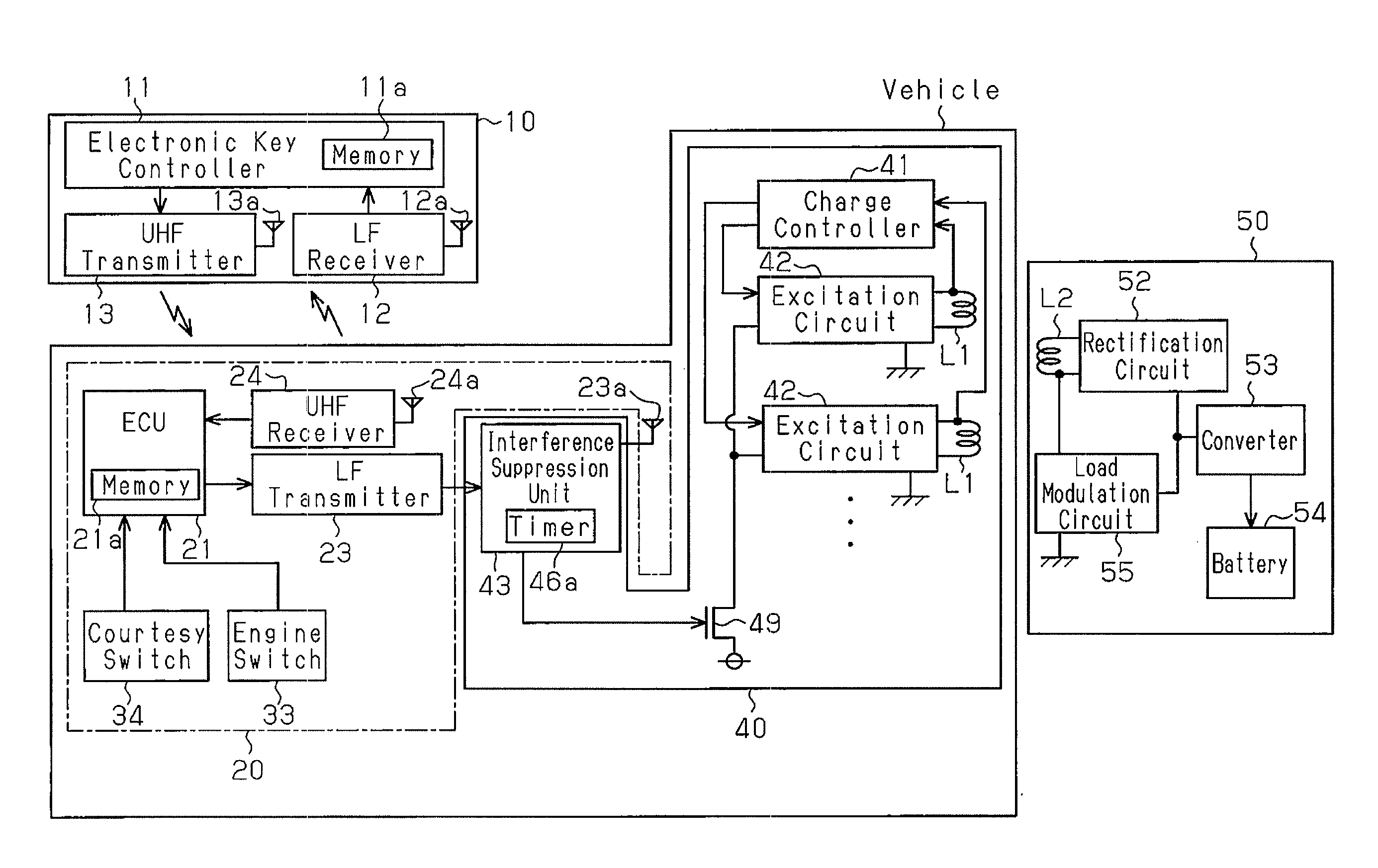
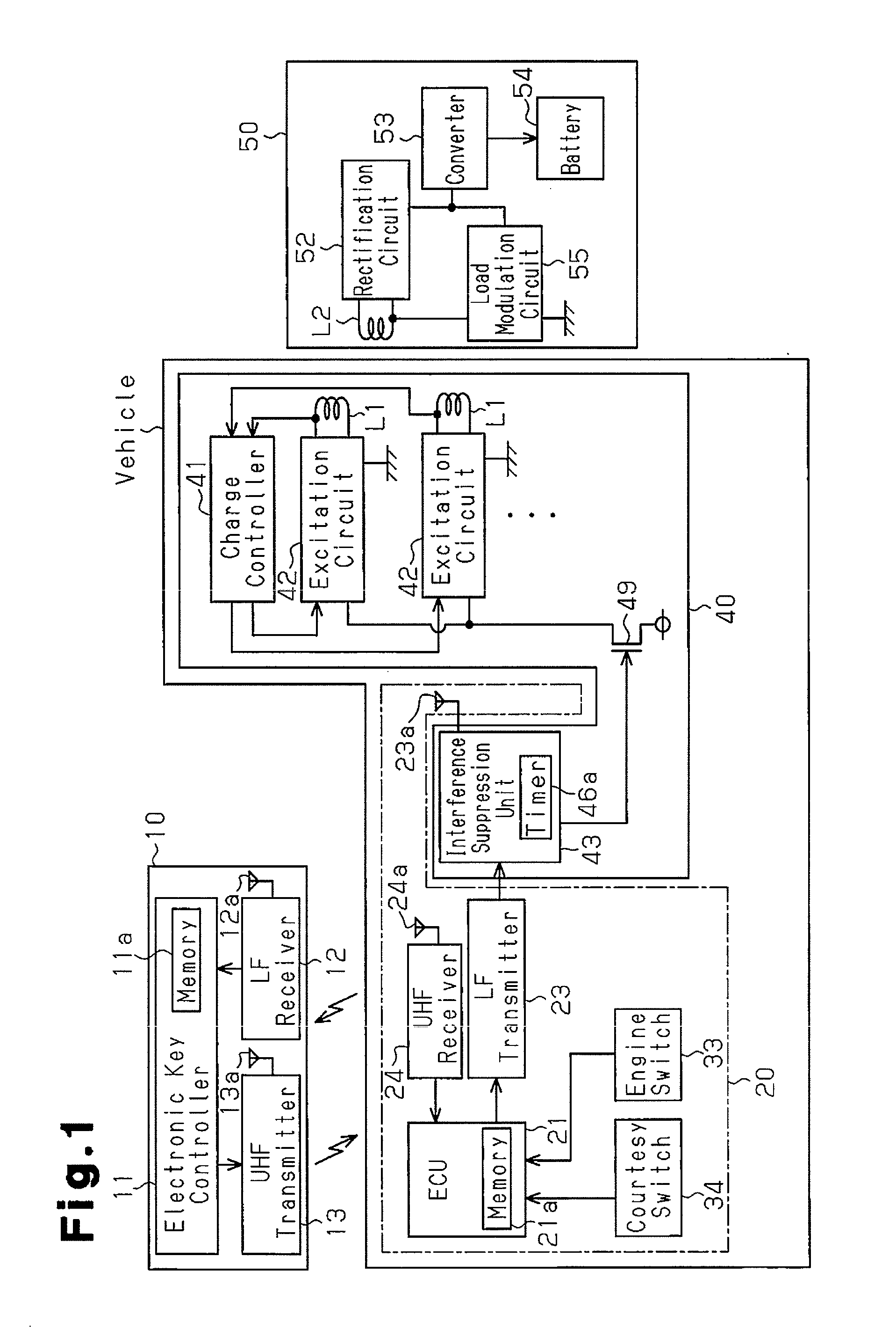
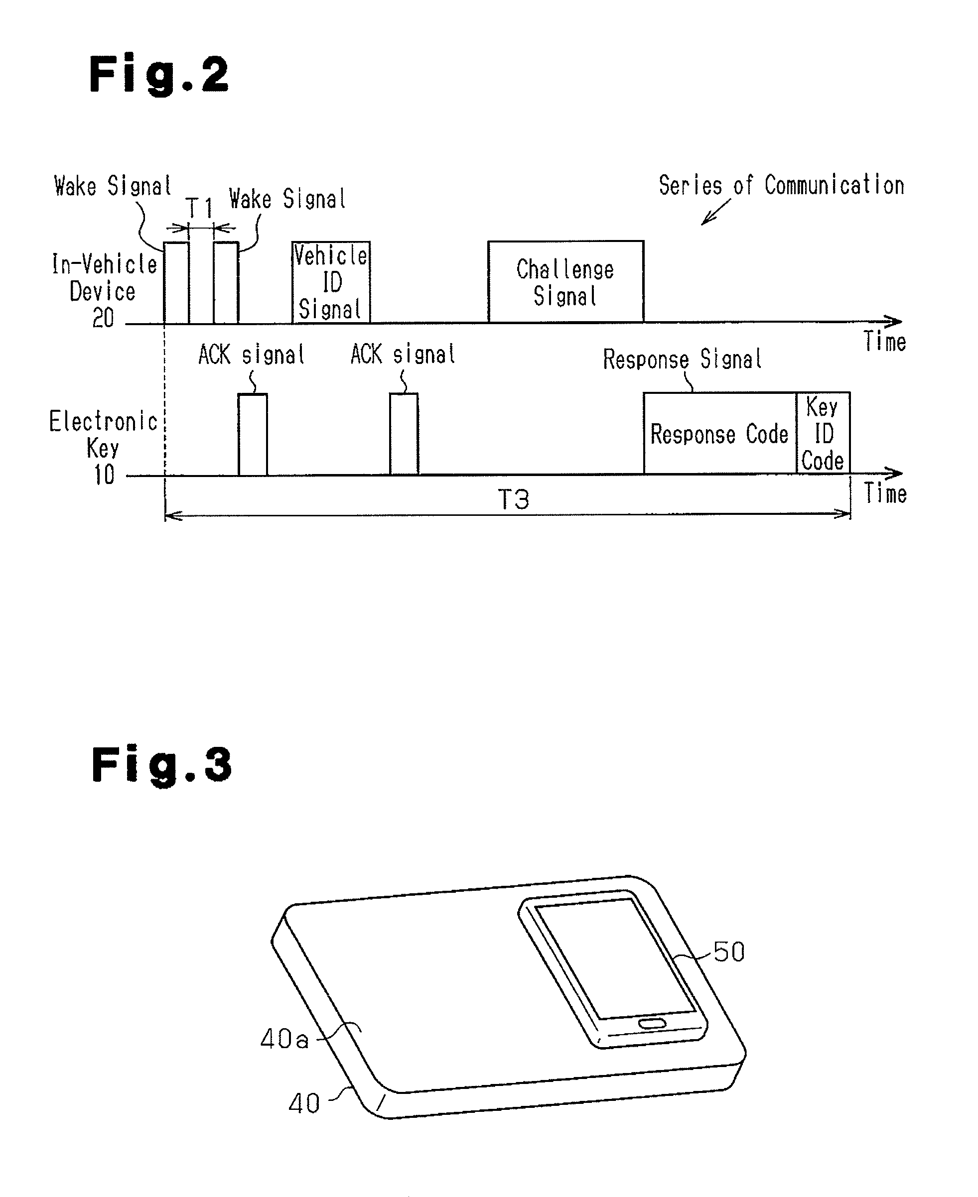
[0020]Referring to FIG. 1, a vehicle includes a wireless charging device 40 and an in-vehicle device 20. The in-vehicle device 20 performs communication with an electronic key 10, which is carried by a user, to permit starting of the engine. The wireless charging device 40 can charge a portable terminal 50, which is carried by the user, in a wireless manner. The structures of the electronic key 10, the in-vehicle device 20, the wireless charging device 40, and the portable terminal 50 will now be described in detail.

[0021]Electronic Key

[0022]The electronic key 10 includes an electronic key controller 11, an LF receiver 12, and an UHF transmitter 13. The electronic key controller 11 is formed by a computer unit, which includes a CPU, and is connected to the LF receiver 12 and the UHF transmitter 13. The LF receiver 12 is connected to a receive...

second embodiment

[0053]A wireless charging device according to a second embodiment of the present invention will now be described with reference to FIG. 5. The second embodiment differs from the first embodiment in how the power supplying suspension time is set. The description hereafter will focus on the differences between the first and second embodiments.

[0054]When the user enters the vehicle and the ECU 21 determines with the courtesy switch 34 that the vehicle door has been opened and closed, the ECU 21 performs the series of communication (verification) for a number of times to determine whether or not the authentic electronic key 10 is located in the vehicle. In this case, as shown in FIG. 5, when a first verification is accomplished, the ECU 21 further performs the series of communication (verification) after an interval of a predetermined time T2.

[0055]In a verification accomplishment state, when recognizing that the engine switch 33 has been operated, the ECU 21 starts the engine. Verifica...


PUM


Abstract

A wireless charging device (40) arranged in a vehicle including an in-vehicle device (20). The in-vehicle device transmits a wake signal in intervals until receiving a response from an electronic key (10) and communicates with the electronic key when receiving the response to determine whether the electronic key is authentic. The wireless charging device includes a primary coil (L1) that transmits power to a charged device (50) when supplied with alternating current. A detection unit (43) uses the wake signal to detect when communication starts between the in-vehicle device and the electronic key. A power supplying suppression unit (43) reduces the alternating current supplied to the primary coil over a certain time from when the communication starts. The power supplying suppression time includes the time required for a series of communication to be performed between the in-vehicle device and the electronic key for the verification.

Description

TECHNICAL FIELD[0001]The present invention relates to a wireless charging device, which performs wireless charging on a charged device, and a method for controlling wireless charging.BACKGROUND ART[0002]A wireless charging system transmits power from a charging device to a charged device in a wireless manner to charge the charged device (refer to, for example, Japanese Laid-Open Patent Publication No. 2008-5573). More specifically, the charging device includes a primary coil, and the charged device includes a secondary coil. The charged device is set on a power transmission pad, which is formed on an upper surface of the charging device. When excited, the primary coil generates low-frequency radio waves (electromagnetic waves), which induce power at the secondary coil. The power charges a battery that is incorporated in the charged device.[0003]It is expected that many charging devices will be manufactured in compliance with a standard set by the Wireless Power Consortium (WPC), whi...

Claims


Application Information

Patent Timeline
IPC IPC(8): H02J7/02H02J7/00
CPCH02J7/025H02J7/007H02J2007/0001B60R25/406B60L1/006Y02T90/16H02J50/12H02J7/00045H02J50/80H02J50/70H02J50/10H02J50/20
Inventor OKADA, HIROKIMURAKAMI, HIROKOWATANABE, NAOKIHANAKI, HIDENOBU
Owner KK TOKAI RIKA DENKI SEISAKUSHO
Why Eureka
Try Eureka