
Electromagnetic input device and coil detection circuit thereof

a detection circuit and input device technology, applied in the direction of testing circuits, program control, instruments, etc., can solve the problems of conventional detection devices not being able detection devices neither being able to identify, and conventional detection devices being unable to detect the shorting condition of induction lines, so as to improve the sensing accuracy of electromagnetic input devices.

Active Publication Date: 2015-01-15
WACOM CO LTD
View PDF5 Cites 19 Cited by
  • Summary
  • Abstract
  • Description
  • Claims
  • Application Information

AI Technical Summary

Benefits of technology

The present disclosure improves the accuracy of an electromagnetic input device by using a coil detection circuit that can detect short-circuit and open-circuit defects in adjacent or staggered loop coils. This ensures that the device can accurately detect the desired input.

Problems solved by technology

Although the conventional detection device can detect the induction line opening condition, the detection device neither can identify whether there is an induction line shorting condition occurs in the adjacent or interleaved induction lines nor identify whether the impedance of each of the induction lines falls within a specified range.
If an induction line shorting condition occurs in one induction line and another induction line which is adjacent to or vertically staggered with respect to the induction line, the conventional detection device cannot detect the induction line shorting condition.
In addition to the induction line shorting condition cannot be detected, whether the impedance of each of the induction lines is abnormally high or low cannot be identified either even the induction lines are determined to be normal under the induction line opening condition test.
However, the impedance abnormality in the corresponding induction line will still affect the operation of the input device (such as the touch panel).

Method used


Image

  • Electromagnetic input device and coil detection circuit thereof
  • Electromagnetic input device and coil detection circuit thereof
  • Electromagnetic input device and coil detection circuit thereof

Examples


Embodiment Construction

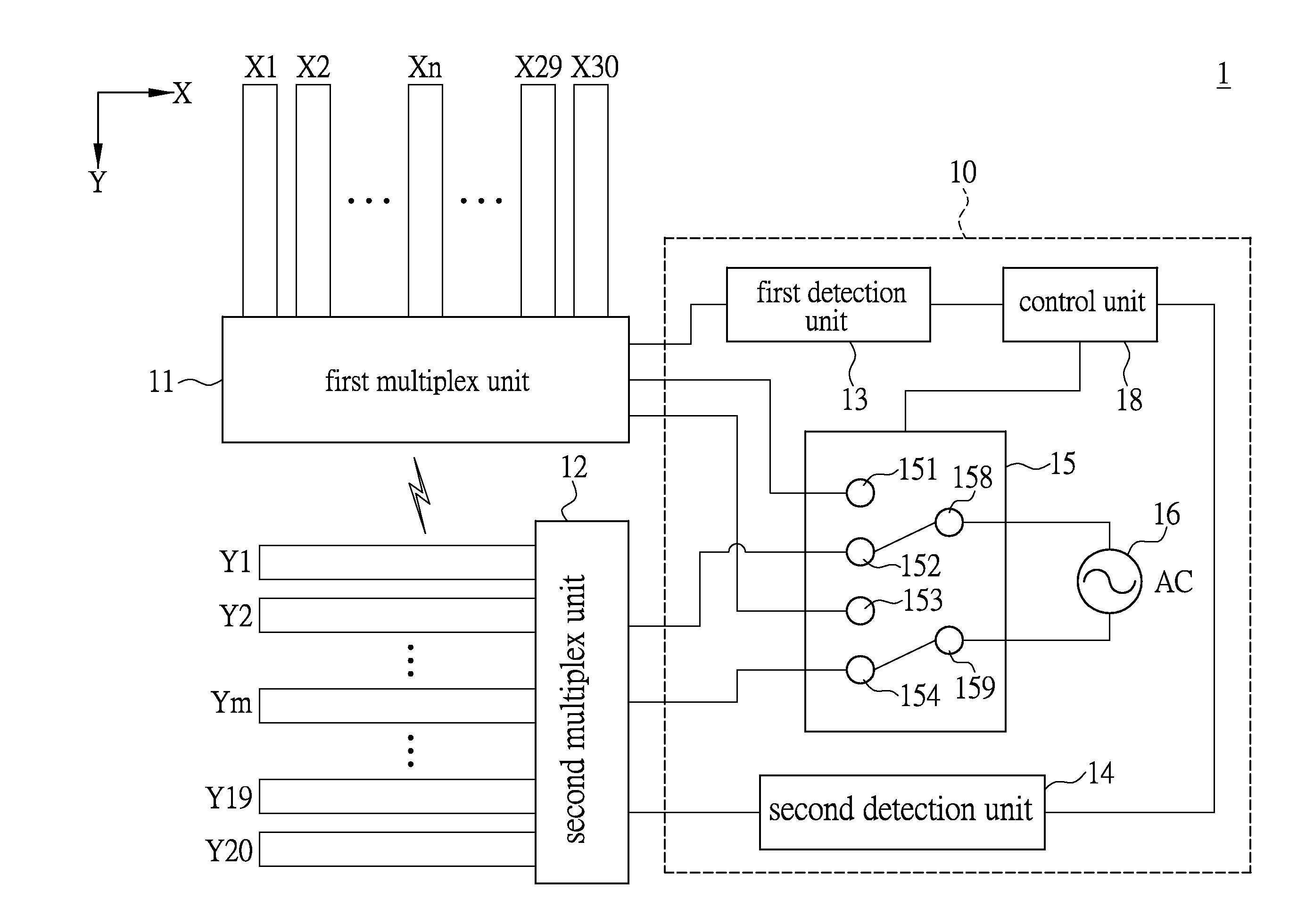
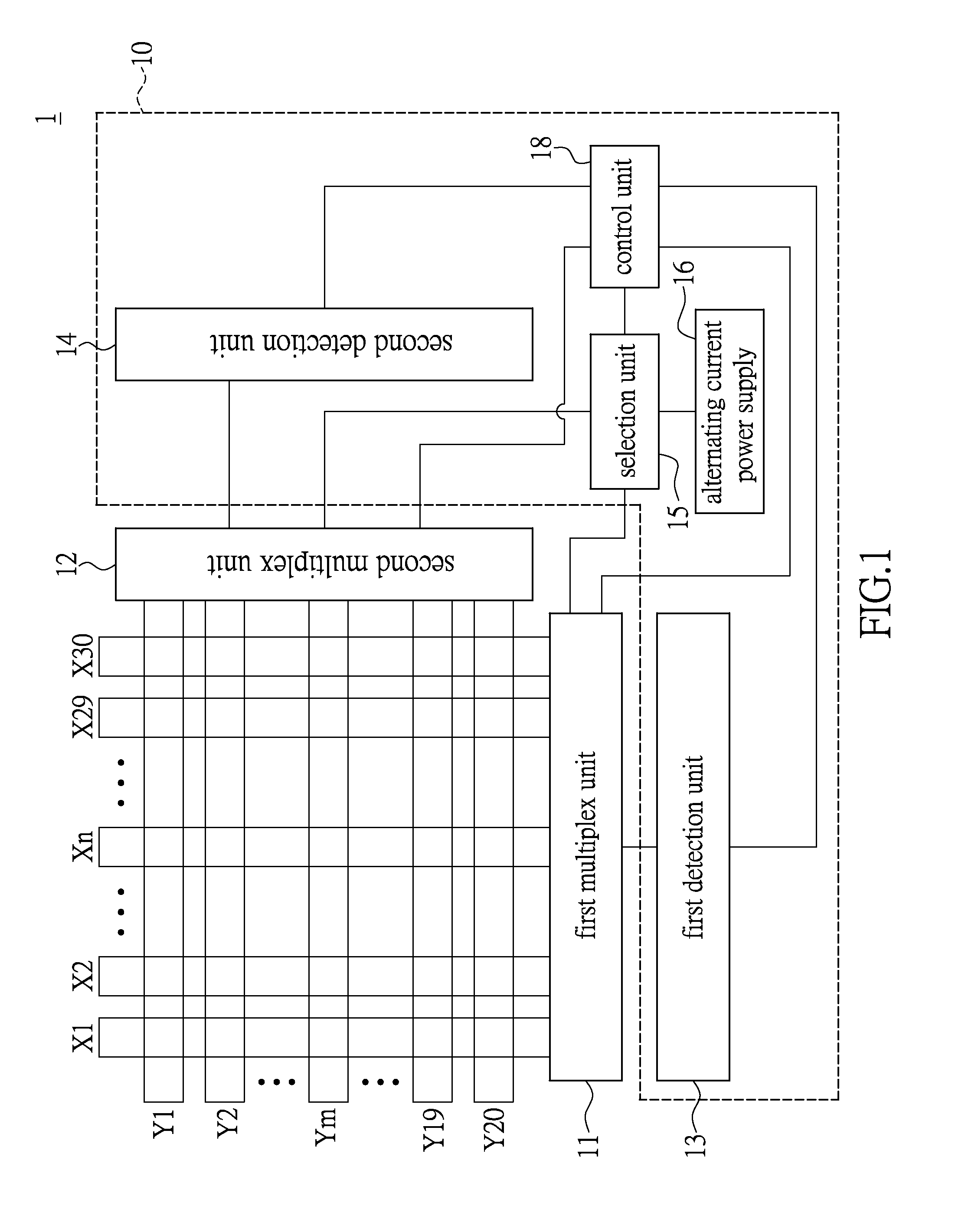
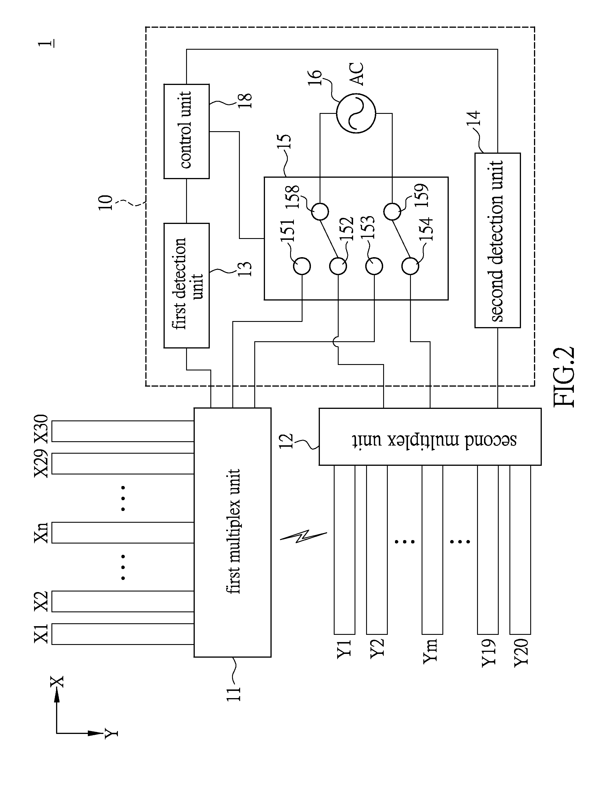
[0017]FIG. 1 is a functional block diagram of a coil detection circuit of an electromagnetic input device in an embodiment of the present disclosure. Please refer to FIG. 1. An electromagnetic input device 1 comprises a plurality of first loop coils X1-X30, a plurality of second loop coils Y1-Y20, a coil detection circuit 10, a first multiplex unit 11 and second multiplex unit 12. In practice, the electromagnetic input device 1 is, for example, a computer graphics tablet, a computer handwriting tablet, a computer digital tablet or an electronic whiteboard; however, in the present disclosure, the electromagnetic input device 1 is not limited thereto.

[0018]For easy illustration, in the present embodiment, the first loop coils X1-X30 are an electromagnetic induction antenna loop in X-axis direction, and the second loop coils Y1-Y20 are an electromagnetic induction antenna loops in Y-axis direction. In another embodiment, the first loop coils X1-X30 can be an electromagnetic induction a...


PUM


Abstract

A coil detection circuit thereof for an electromagnetic input device including a plurality of first loop coils and second loop coils includes a first detection unit, a second detection unit and a selection unit. When the selection unit selects one the first loop coils to emit an electromagnetic signal for each one of the second loop coils, each one of the second loop coils forms a second closed loop for receiving the electromagnetic signal, and the second detection unit detects a second signal. When one of the second loop coils forms an open circuit or short circuit, the second detection unit detects an open-circuit signal or a short-circuit signal.

Description

BACKGROUND[0001]1. Technical Field[0002]The present disclosure relates to an electromagnetic input device and a coil detection circuit thereof, in particular, to an electromagnetic input device having a plurality of loop coils, and a coil detection circuit thereof.[0003]2. Description of Related Art[0004]People can interact with electronic devices via an input device, such as a touch panel, wherein the touch panels with advances in technology, have been widely used in electronic devices, such as smart phones, tablet computers, auto teller machines (ATMs) or computer graphics tablets, etc. Thus, people can easily touch the touch panel to generate an input signal to an electronic device so as to enhance the ease of operation of the electronic device[0005]However, to enhance the touch sensing ability of the touch panel, the induction lines in touch panel are closely distributed in a certain area of the transparent conductive film, such as an indium tin oxide (ITO) film, or in a certain...

Claims


Application Information

Patent Timeline
IPC IPC(8): G01R31/02
CPCG01R31/025G06F3/04164G06F3/04166G06F3/046G01R27/267G05B2219/37289
Inventor YEH, CHIA-JUI
Owner WACOM CO LTD
Learn More