Foot cushion mechanism and electronic device therewith

a cushion mechanism and foot technology, applied in the direction of instruments, portable computer details, electric apparatus casings/cabinets/drawers, etc., can solve the problems of insufficient poor convection, and inability to provide sufficient gap so as to enhance the efficiency of heat dissipation of the electronic device, and increase the distance between the housing and the supporting surface

Active Publication Date: 2015-01-15
WISTRON CORP
View PDF3 Cites 18 Cited by
  • Summary
  • Abstract
  • Description
  • Claims
  • Application Information

AI Technical Summary

Benefits of technology

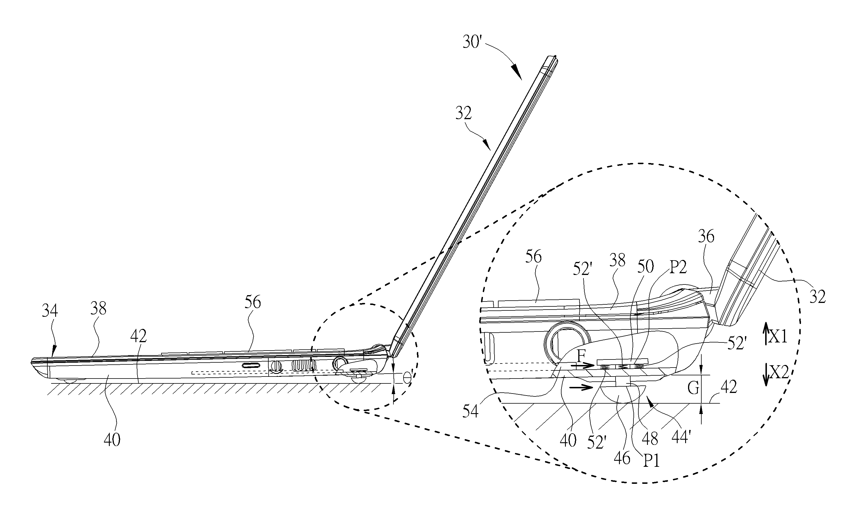
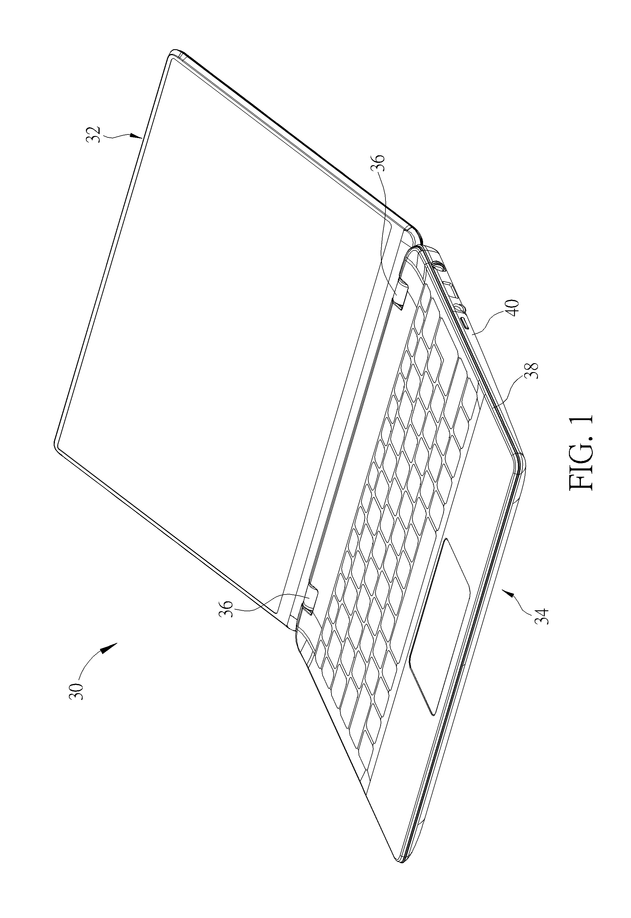
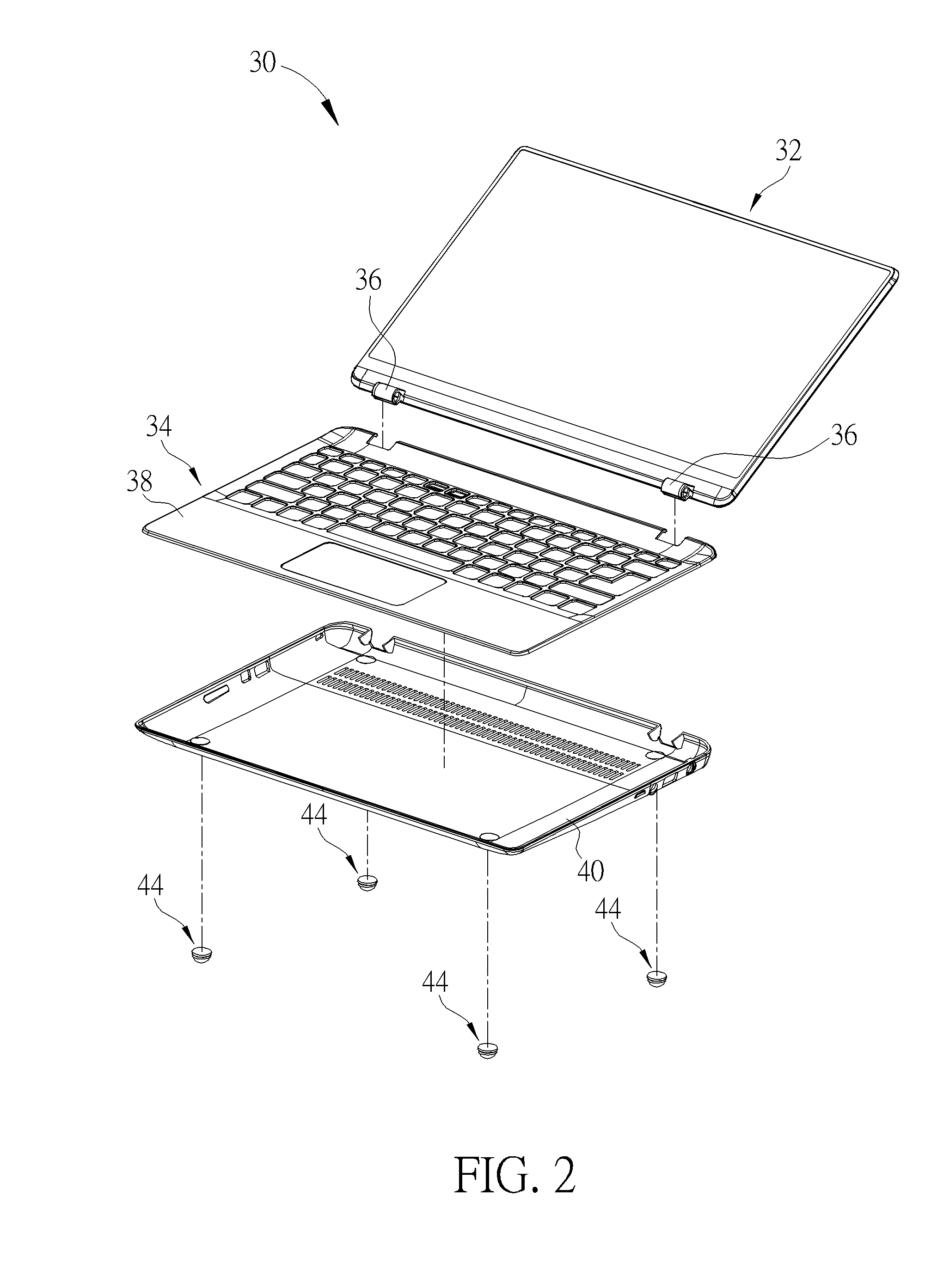
[0019]According to another embodiment of the present invention, an electronic device includes a housing and a foot cushion mechanism. The foot cushion mechanism includes a foot cushion member, a holding base and at least one shape memory material member. The foot cushion member is installed on the housing and abuts against a supporting surface. The holding base and the foot cushion member are respectively installed on opposite sides of the housing. The at least one shape memory material member selectively connects the housing and the holding base or connects the holding base and the foot cushion member. The at least one shape memory material member deforms when being heated due to a shape memory effect, and the housing is driven by the shape memory effect to move away from the foot cushion member such that a distance between the housing and the supporting surface is increased.
[0020]In summary, the shape memory material member of the foot cushion mechanism of the present invention selectively connects the housing and the holding base or connects the holding base and the foot cushion member. When the shape memory material member of the foot cushion mechanism of the present invention is heated, the shape memory material member deforms due to shape memory effect, so as to drive the housing away from the foot cushion member. Accordingly, the distance between the housing and the supporting surface is increased. In other words, the foot mechanism of the present invention is used for lifting the housing for increasing the gap between the housing and the supporting surface, so as to enhance the efficiency of heat dissipation of the electronic device. As a result, the inner temperature of the electronic device drops as functioning and thus performance of the electronic device is enhanced. In addition, the foot cushion mechanism of the present invention can further recover the deformed shape memory material member by applying an external force or by current control, so as to contain the foot cushion mechanism on the electronic device for keeping aesthetic feeling of the electronic device.

Problems solved by technology

However, the notebook computer recently has a trend of design with thin size and light weight, which constrains a thickness of the cushion.
Thus, a sufficient gap between the housing and the supporting surface can not be provided.
Accordingly, it results in poor convection and poor heat dissipation of the notebook computer.
As a result, it causes inner temperature of the notebook computer to rise and thus affects performance of the notebook computer.

Method used


Image

  • Foot cushion mechanism and electronic device therewith
  • Foot cushion mechanism and electronic device therewith
  • Foot cushion mechanism and electronic device therewith

Examples


Embodiment Construction

[0038]In the following detailed description of the embodiments, reference is made to the accompanying drawings which form a part hereof, and in which is shown by way of illustration specific embodiments in which the invention maybe practiced. In this regard, directional terminology, such as “top,”“bottom,” etc., is used with reference to the orientation of the Figure(s) being described. The components of the present invention can be positioned in a number of different orientations. As such, the directional terminology is used for purposes of illustration and is in no way limiting. On the other hand, the drawings are only schematic and the sizes of components may be exaggerated for clarity. It is to be understood that other embodiments maybe utilized and structural changes may be made without departing from the scope of the present invention. Also, it is to be understood that the phraseology and terminology used herein is for the purpose of description and should not be regarded as l...


PUM


Abstract

A foot cushion mechanism with lifting function is disclosed. The foot cushion mechanism includes a foot cushion member, a holding base and at least one shape memory material member. The foot cushion member is installed on a housing and abuts against a supporting surface. The holding base and the foot cushion member are respectively installed on opposite sides of the housing. The at least one shape memory material member selectively connects the housing and the holding base or connects the holding base and the foot cushion member. The at least one shape memory material member deforms when being heated due to a shape memory effect, and the housing is driven by the shape memory effect to move away from the foot cushion member such that a distance between the housing and the supporting surface is increased.

Description

BACKGROUND OF THE INVENTION[0001]1. Field of the Invention[0002]The present invention relates to a foot cushion mechanism and an electronic device therewith, and more particularly, to a foot cushion mechanism with lifting function and an electronic device therewith.[0003]2. Description of the Prior Art[0004]Generally speaking, a cushion of a notebook computer supports a housing of the notebook computer on a supporting surface, such as a desk, so as to form a gap between the housing and the supporting surface. The gap provides the notebook computer with a space for a heat dissipating module of the notebook computer to dissipate heat in a convective manner. However, the notebook computer recently has a trend of design with thin size and light weight, which constrains a thickness of the cushion. Thus, a sufficient gap between the housing and the supporting surface can not be provided. Accordingly, it results in poor convection and poor heat dissipation of the notebook computer. As a re...

Claims


Application Information

Patent Timeline
Patent Type & Authority Applications(United States)
IPC IPC(8): G06F1/16F03G7/06
CPCG06F1/166F03G7/065G06F1/1616G06F1/203
Inventor FU, CHUAN-CHENGCHEN, HUNG-LI
Owner WISTRON CORP
Why Eureka
Try Eureka