Device for use in glaucoma surgery

a glaucoma and glaucoma surgery technology, applied in the field of glaucoma surgery devices, can solve the problems of difficult use, risk of misplacement and/or “wandering", etc., and achieve the effect of lowering the abnormal elevation of intraocular pressure, easy use, and low cos

Inactive Publication Date: 2015-01-15
GEUDER AG
View PDF14 Cites 14 Cited by
  • Summary
  • Abstract
  • Description
  • Claims
  • Application Information

AI Technical Summary

Benefits of technology

[0013]Therefore, the object of the present invention is to provide a device that is intended for use in glaucoma surgery, for implantation in the eye and that is as easy as possible to use and at the same time is safe and can be implanted for the purpose of lowering the abnormal elevation of the intraocular pressure. Another object of the present invention is to guarantee a secure seat in the implanted state, i.e. in the eye. Finally the device shall be inexpensive to manufacture.
[0015]The head region is an extremely flat region, which is constructed like a flat nail head or the head of a thumbtack. As a result, the head region forms a bearing surface with its bottom side and, therefore, makes it possible to position the probe with very high precision.
[0018]Working on the aforesaid, the device according to the invention is based on the idea of draining, not in accordance with the common practice known from the prior art, the fluid from the anterior chamber of the eye. On the contrary, the object of the invention is to place the glaucoma shunt where the abnormal elevation of the intraocular pressure acts, in particular, in the posterior chamber of the eye. Correspondingly the device with the probe is dimensioned in such a way that it can be inserted through the sclera as far as into the posterior chamber of the eye, so that a flow communication between the posterior chamber of the eye is established outwards. After the insertion of the device, the special function of the head region is important, because the conjunctiva is closed again by means of the head region and is routinely sutured. Consequently the originally opened conjunctival flap covers the upper side of the head region, so that drainage from the posterior chamber into a space between the conjunctiva and the sclera is achieved.
[0020]In order not to provoke a detachment of the retina, the pars plana region lends itself to the implantation. After the preparation or rather the opening of the conjunctiva, it is possible to place with a minimum of effort one or more shunts in the form of the device according to the invention, i.e. in the form of very small and flat trocars, under the conjunctiva. After the placement of the trocars, the conjunctival flap, which is created in the direction of the opening, can be closed again by means of the trocar head(s) and sutured, so that the device according to the invention can be used for drainage into the space between the conjunctiva and the sclera.
[0021]The head region is concavely curved in an advantageous way at least on the bottom side, i.e. on the side facing the probe, in conformity with the geometry of the eye. As a result, a secure seat of the device directly at or on the sclera is possible. It is also advantageous, if the head region is configured so as to be at least slightly convex on the upper side, i.e. on the side facing away from the probe. This feature facilitates the covering of the head region with the conjunctiva or more specifically the conjunctival flap.

Problems solved by technology

The devices, which are known from practical use for lowering the abnormal elevation of the intraocular pressure, are difficult to use, in particular during the implantation.
In addition, there is also the risk of misplacement and / or “wandering.”

Method used


Image

  • Device for use in glaucoma surgery
  • Device for use in glaucoma surgery
  • Device for use in glaucoma surgery

Examples


Embodiment Construction

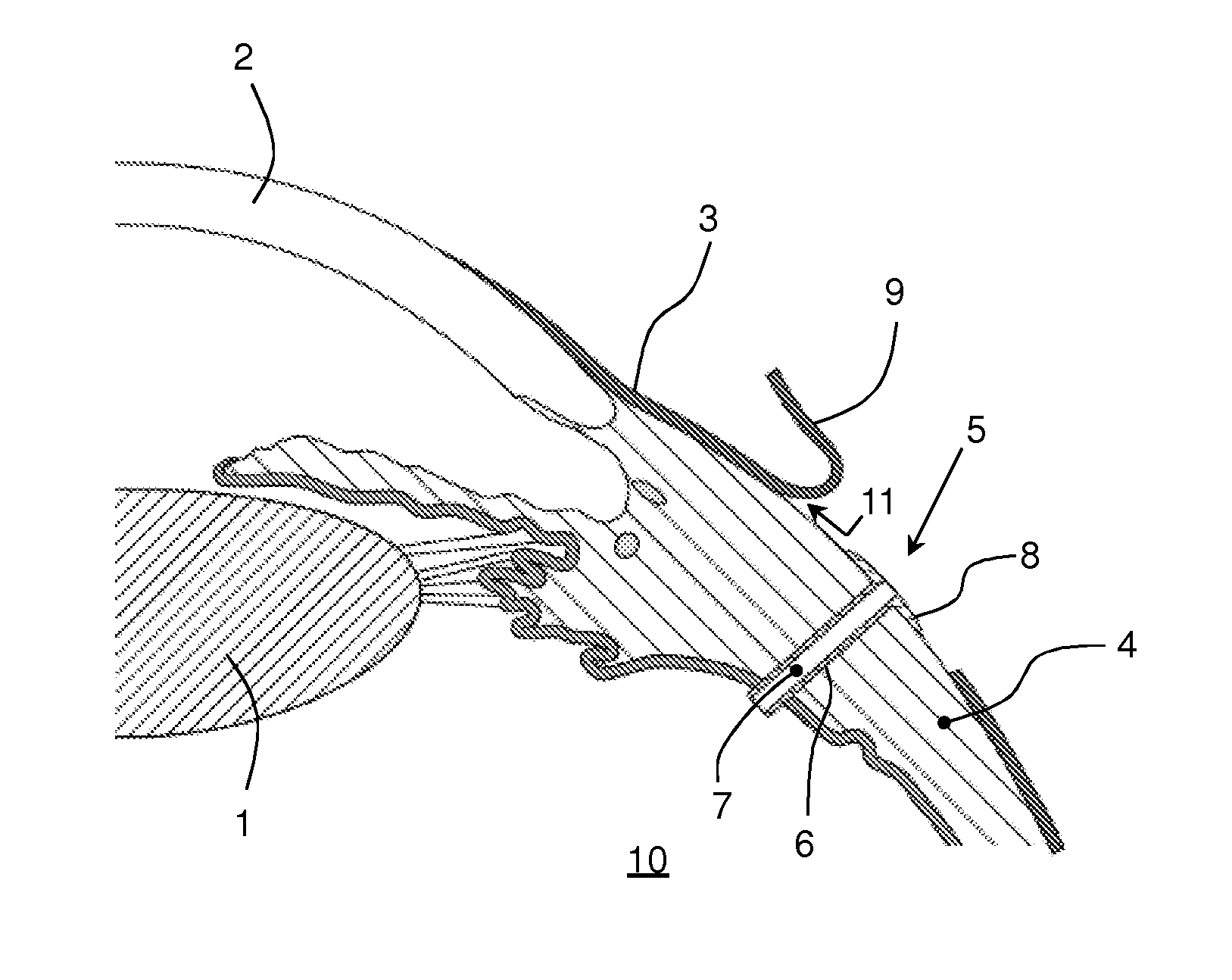
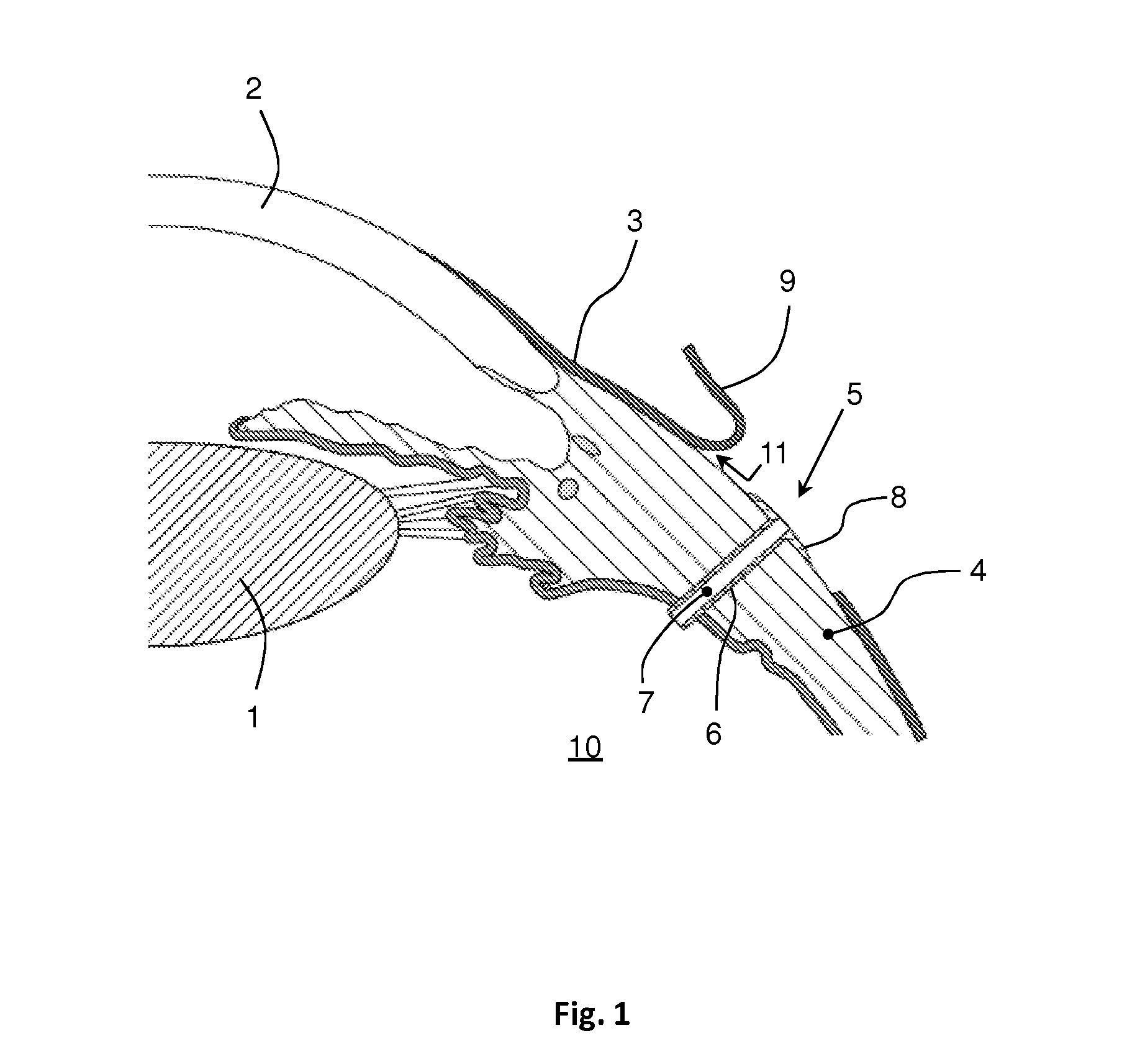
[0028]FIGS. 1 and 2 show in schematic form a sectional view of a part of the human eye in a highly simplified representation, where the lens 1, the cornea 2, the conjunctiva 3 and the sclera 4 are marked as the essential components.

[0029]In the drawing from FIG. 1, the inventive device 5 is inserted for implant purposes while the conjunctiva 3 is open in such a way that the probe 6 extends completely through the sclera 4. The relief channel 7, which is open on both sides, extends through the probe 6.

[0030]The insertion of the device 5 or more specifically the probe 6 is defined by the head region 8. To put it more succinctly, the head region 8 sits with its bottom side close to the sclera 4.

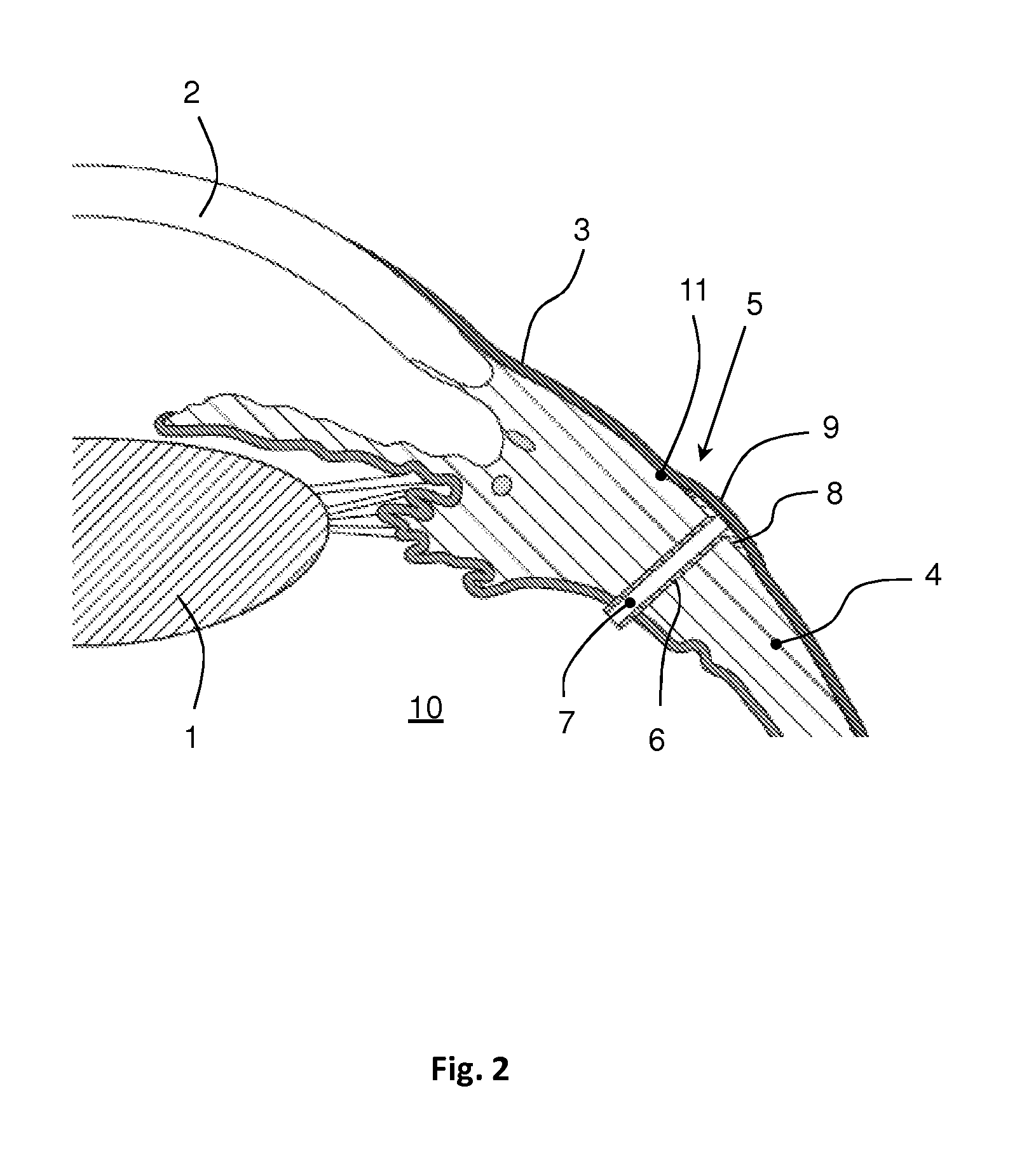
[0031]According to the drawing in FIG. 2, the flap 9, which is made in order to open the conjunctiva 3, is placed over the head region 8 of the device 5; and the conjunctiva 3 is sutured. In this way the device 5 is implanted in its entirety, with the result that a drainage system is created betw...


PUM


Abstract

The invention relates to a device for use in glaucoma surgery intended for implantation in the eye. The device comprises a flat head region (8), a probe (6) which adjoins the head region (8), and a relief channel (7) which extends through the head region (8) and the probe (6) and is open at both sides. The design and dimensions of the head region (8) and of the probe (6) are such that the probe (6) can be inserted by its free end through the sclera (4) into the posterior chamber (10) of the eye in order to reduce an excessive intraocular pressure when the conjunctiva (3) is open, and such that, in the inserted position, the lower side of the head region (8) comes into abutment with the sclera (4), and the upper side of the head region (8) can be covered by closing the conjunctiva (3) such that drainage can be performed from the posterior chamber (10) into a gap (11) between the conjunctiva (3) and the sclera (4).

Description

CROSS REFERENCE TO RELATED APPLICATIONS[0001]This application is a national stage application, filed under 35 U.S.C. §371, of International Application No. PCT / DE2013 / 200001, filed Jan. 9, 2013, which claims priority to German Application No. 10 2012 200 411.4, filed Jan. 12, 2012, both of which are hereby incorporated by reference in their entirety.BACKGROUND[0002]1. Technical Field[0003]The invention relates to a device for use in glaucoma surgery, in particular, for implantation in the eye. Furthermore, the invention relates to the use of such a device in glaucoma surgery that is intended for implantation in the eye as well as a method for using a corresponding device in glaucoma surgery that is intended for implantation in the eye, for the purpose of lowering the abnormal elevation of the intraocular pressure.[0004]The device is intended for use in glaucoma surgery, in particular, for the surgical treatment of glaucoma. The term “glaucoma” includes a group of ocular diseases of ...

Claims


Application Information

Patent Timeline
Patent Type & Authority Applications(United States)
IPC IPC(8): A61F9/007
CPCA61F9/00781
Inventor HATTENBACH, LARS-OLOF
Owner GEUDER AG
Why Eureka
Try Eureka